Method and System for Acquiring an X-Ray Image

a technology of x-ray images and x-ray images, applied in the field of methods and systems for acquiring x-ray images, can solve the problems of requiring a certain amount of time and cannot be continued without, and achieve the effects of optimizing the display of x-ray images, removing noise or artifacts, and good image quality

Inactive Publication Date: 2014-09-18
SIEMENS AG
View PDF3 Cites 15 Cited by
  • Summary
  • Abstract
  • Description
  • Claims
  • Application Information

AI Technical Summary

Benefits of technology

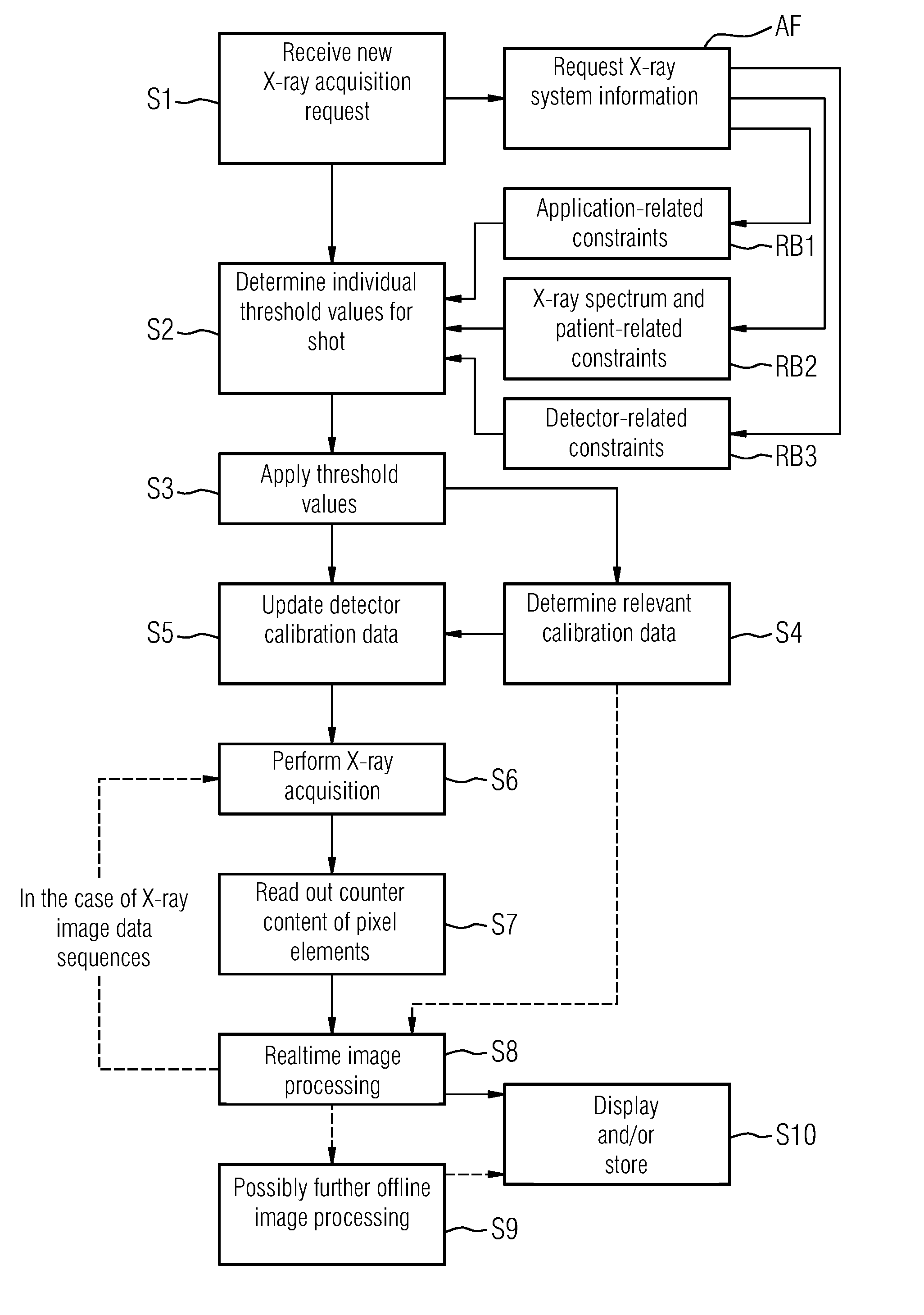
[0015]For each newly planned X-ray shot, one or more individual threshold values are determined for the pixel elements. The threshold values may be selected or adjusted to the radiographic situation and conditions, so that improved X-ray imaging with higher image quality may be achieved. The selection or adjustment also enables the X-ray dose to be better utilized, which allows the X-ray dose to be reduced, thereby exposing the patient and doctor to a lower radiation load. In addition, various special applications, such as K-edge imaging, that are only possible to a limited extent under standard conditions, may be implemented with good X-ray quality. Via a single X-ray detector, different types of shots may be implemented in quick succession with high image quality using, e.g., different X-ray spectra. For example, the same threshold value(s) may be determined for all of the pixel elements. Alternatively, individual threshold values may be determined, respectively, for each pixel element.
[0024]According to one embodiment, the image data representing the X-ray image undergoes image processing and / or image correction. Such image processing or correction serves to further optimize the display of the X-ray images, e.g., by removing noise or artifacts from the image data, so that a doctor may easily obtain relevant information from the X-ray images for diagnosis or treatment.

Problems solved by technology

This reading process involves a certain amount of time, during which counting cannot continue without errors.

Method used


Image

  • Method and System for Acquiring an X-Ray Image
  • Method and System for Acquiring an X-Ray Image
  • Method and System for Acquiring an X-Ray Image

Examples


Embodiment Construction

[0037]FIG. 8 and FIG. 9 show two different X-ray spectra typical for X-ray imaging, both prior to and after irradiation of an examination subject. A first X-ray spectrum R1 has a higher maximum X-ray energy than a second X-ray spectrum R2, resulting, e.g., from a higher tube voltage of the X-ray tube used. In addition, the X-ray spectra are also shown after two different hardenings a and b at the detector input. Depending on the tube voltage, and pre-filtering of the X-ray radiation and filtering by examination subject and possibly other objects, such as the patient table, the X-ray spectrum is hardened to a lesser or greater degree. FIG. 8 shows a first input X-ray spectrum R1a hardened to a degree a and a first input X-ray spectrum R1b hardened to a degree b. FIG. 9 shows a second input X-ray spectrum R2a hardened to a degree a and a second input X-ray spectrum R2b hardened to a degree b. For many X-ray spectra, image quality may be adversely affected if an X-ray detector has, e.g...


PUM

PropertyMeasurementUnit
quantum efficiencyaaaaaaaaaa
thicknessaaaaaaaaaa

Abstract

A method acquires an X-ray image via a counting digital X-ray detector of an X-ray system. The X-ray detector has an X-ray converter for converting X-ray radiation into an electrical signal and a matrix having a plurality of counting pixel elements. At least one variable threshold value is applied for each pixel element such that an incoming signal is counted by a memory unit in each instance that the incoming signal exceeds the threshold value. The method includes receiving a request to acquire one or more X-ray images, automatically determining one or more threshold values individually adjusted to the X-ray image(s), setting the threshold values in the X-ray detector, applying X-ray radiation while the threshold values are applied, converting X-ray quanta into count signals, storing the count signals in the X-ray detector, outputting image data representing the X-ray image from the X-ray detector, and displaying or storing the X-image.

Description

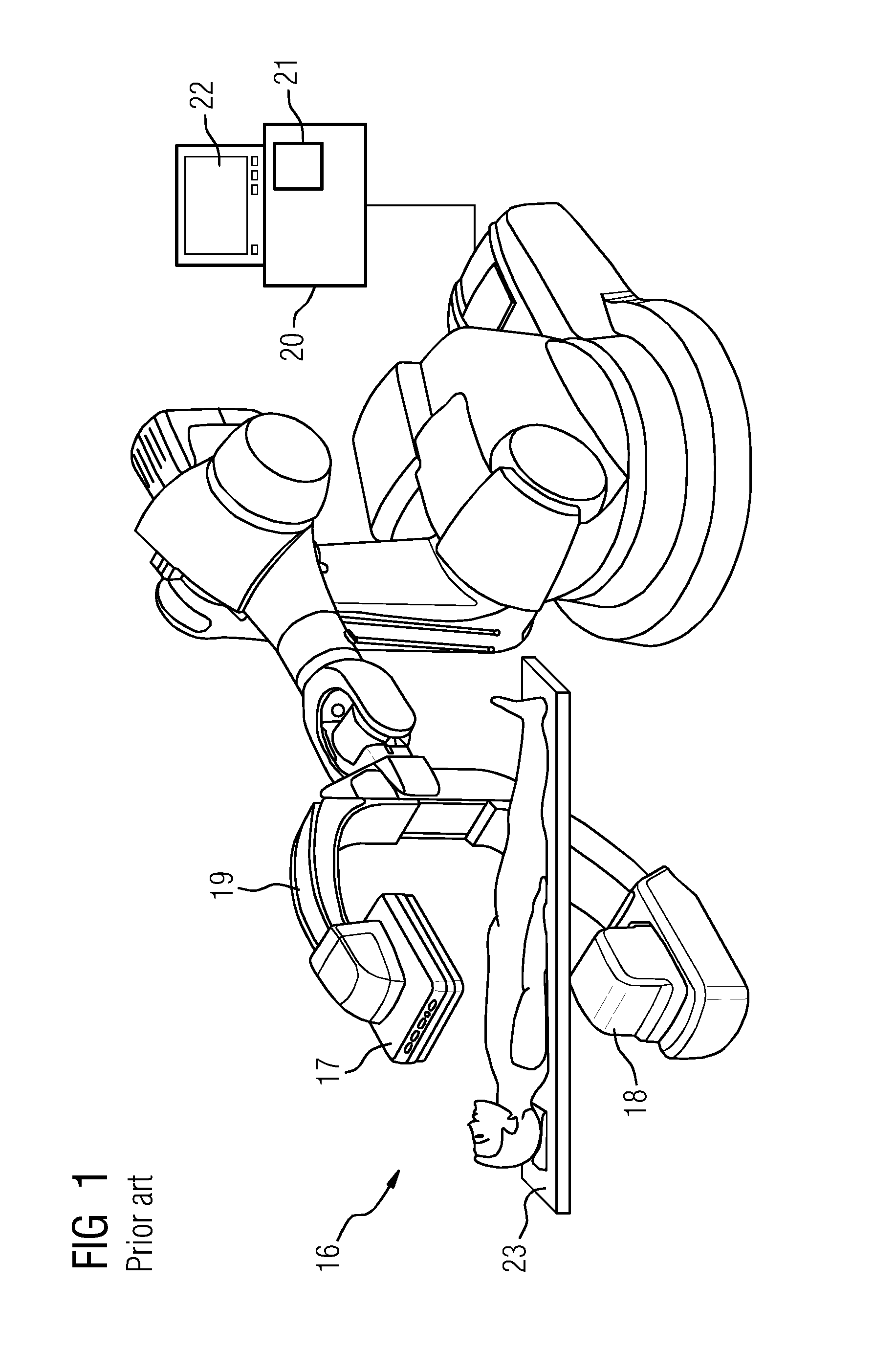
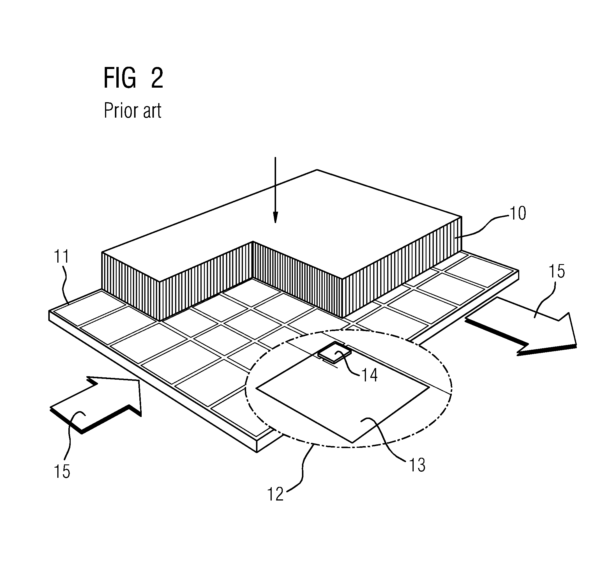
[0001]This application claims the benefit of DE 102013204264.7, filed on Mar. 12, 2013, which is hereby incorporated by reference in its entirety.BACKGROUND[0002]The disclosed embodiments relate to a method and a device for acquiring an X-ray image of an examination subject using a counting digital X-ray detector.[0003]X-ray systems are used for imaging in diagnostic examination and interventional procedures (e.g., in cardiology, radiology and surgery). As shown in FIG. 1, x-ray systems 16 include an X-ray tube 18 and an X-ray detector 17, both mounted, for example, on a C-arm 19. X-ray systems further include a high-voltage generator for producing the tube voltage, an imaging system 21 (often including at least one monitor 22), a system control unit 20 and a patient table 23. Systems having two levels (two C-arms) are also used in interventional radiology. Flat panel detectors are used as X-ray detectors in many fields of medical X-ray diagnostics and intervention, such as radiogra...

Claims


Application Information

Patent Timeline
Patent Type & Authority Applications(United States)
IPC IPC(8): G01N23/04
CPCG01N23/04G01T1/20A61B6/00A61B6/4233A61B6/4241A61B6/4441A61B6/482A61B6/542A61B6/585
Inventor SPAHN, MARTIN
Owner SIEMENS AG
Why Eureka
Try Eureka