Combined fan and ejector cooling

a technology of ejector and combined fan, which is applied in the direction of muffle furnace, lighting and heating apparatus, furnaces, etc., can solve the problems of high power loss, high drawbacks, and extremely uneven heating of the furnace chamber and the loading space in particular, and achieve the effect of improving the pressing arrangemen

Active Publication Date: 2014-09-18
QUINTUS TECH
View PDF7 Cites 6 Cited by
  • Summary
  • Abstract
  • Description
  • Claims
  • Application Information

AI Technical Summary

Benefits of technology

[0014]A general object of the present invention is to provide an improved pressing arrangement, which eliminates or at least reduces at least one of the above mentioned problems.
[0015]In particular, it is an object of the present invention to provide a pressing arrangement and method for such an arrangement capable of rapid and uniform cooling of a load.
[0016]Another object of the present invention is to provide a pressing arrangement and method for such an arrangement capable of rapid and uniform cooling of a load at the same time as improved temperature stability is achieved.

Problems solved by technology

The inlet for the mixed gas into the loading space is thus very small, typically 100 mm in diameter, whereas the diameter of the loading space is typically about 1.2 m. Even though a satisfactory cooling may be achieved, this construction also has drawbacks.
During the pressing operation, when the furnace chamber is to be heated, the heating of the furnace chamber, and the loading space in particular, would become extremely uneven because of the small inlet area to the loading space, unless heating elements are provided on the side of the furnace chamber.
However, this solution is associated with drawbacks.
One problem with this approach is that cold pressure medium always will be drawn into the inner convection loop as soon as circulation is started (by starting the fan).
This will inevitably lead to high losses of power and may also affect the capacity of the heat exchanger in a negative way.

Method used


Image

  • Combined fan and ejector cooling
  • Combined fan and ejector cooling
  • Combined fan and ejector cooling

Examples


Embodiment Construction

[0071]The following is a description of exemplifying embodiments of the present invention. This description is intended for the purpose of explanation only and is not to be taken in a limiting sense. It should be noted that the drawings are schematic and that the pressing arrangements of the described embodiments may comprise features and elements that are, for the sake of simplicity, not indicated in the drawings.

[0072]Embodiments of the pressing arrangement according to the present invention may be used to treat articles made from a number of different possible materials by pressing, in particular by hot isostatic pressing.

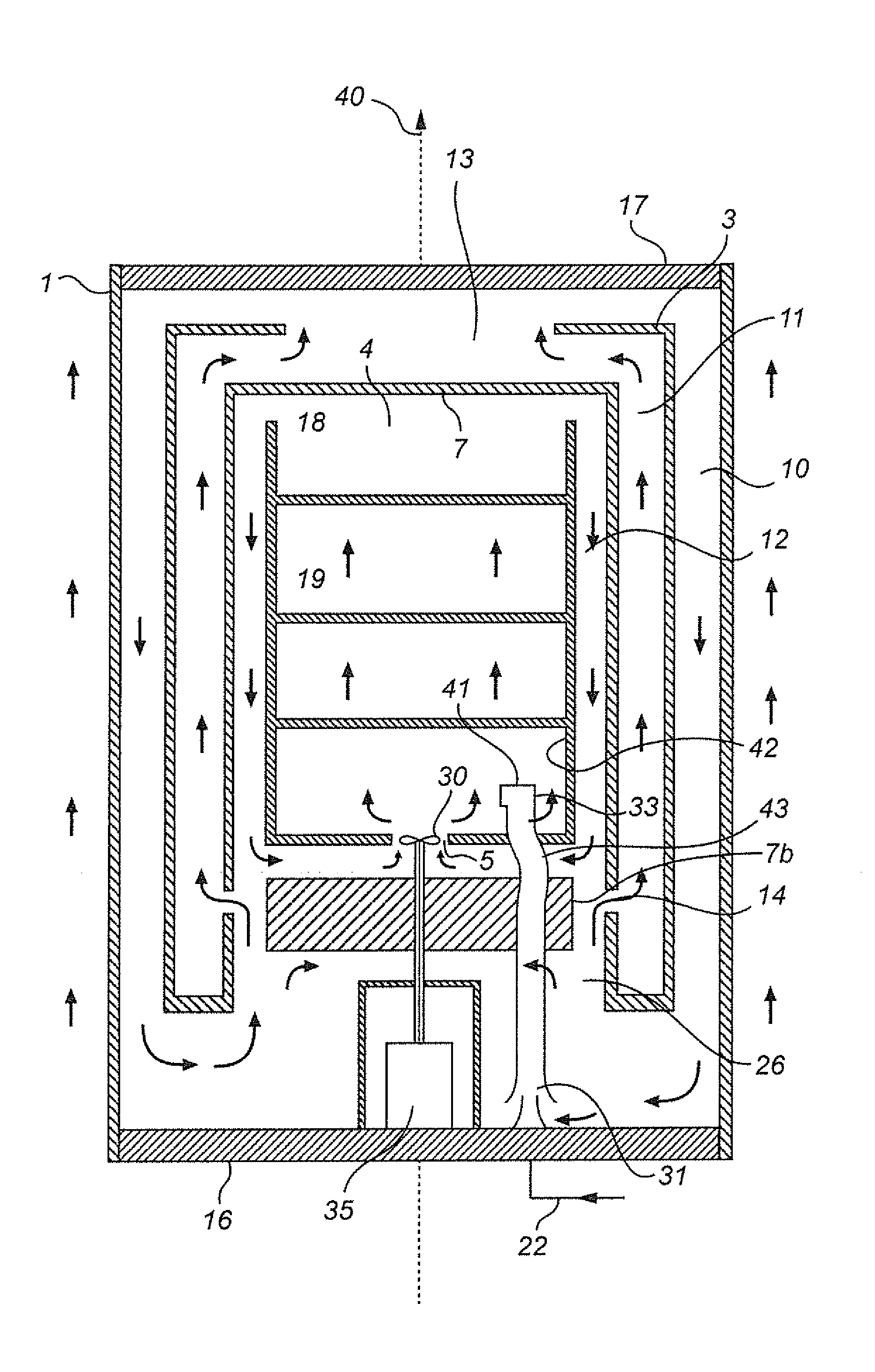
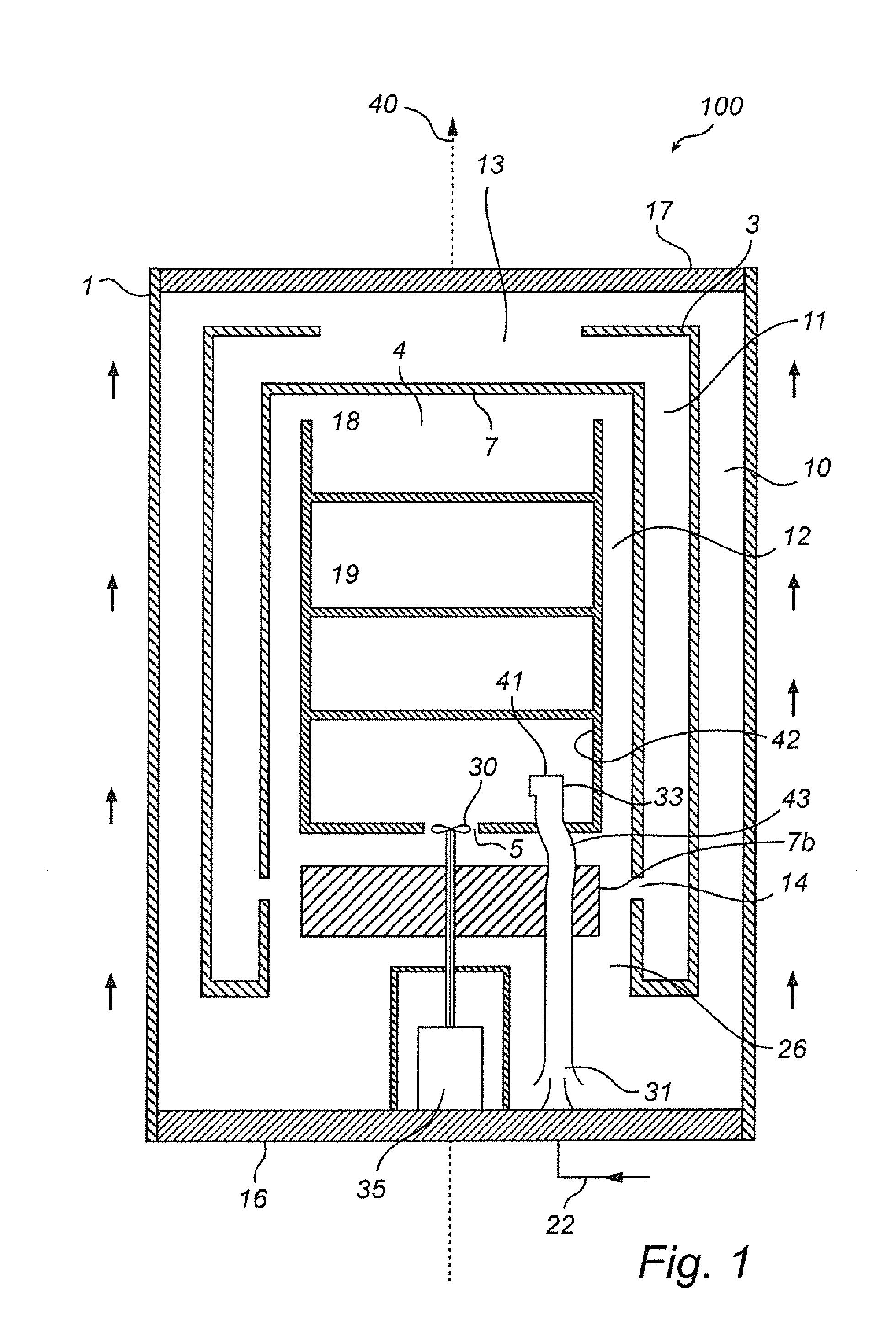
[0073]FIG. 1 shows a pressing arrangement according to an embodiment of the invention. The pressing arrangement 100, which is intended to be used for pressing of articles, comprises a pressure vessel 1 with means (not shown), such as one or more ports, inlets and outlets, for supplying and discharging a pressure medium. The pressure medium may be a liquid or gas...


PUM

PropertyMeasurementUnit
temperaturesaaaaaaaaaa
pressuresaaaaaaaaaa

Abstract

A pressing arrangement for treatment of articles by hot pressing includes a pressure vessel including a furnace chamber and a furnace to hold the articles. A fan circulates a pressure medium within the furnace chamber, and enhances an inner convection loop at a load compartment. The inner convection loop pressure medium has an upward flow through the load compartment, and a downward flow along a peripheral portion of the furnace chamber. A flow generator generates a flow of pressure medium into the load compartment downstream the fan to enhance the inner convection loop. The flow is generated by transporting the pressure medium upwards from a space below a bottom insulating portion and above a bottom end portion, and by injecting the pressure medium into the load compartment downstream the fan to enhance the inner convection loop.

Description

FIELD OF THE INVENTION[0001]The present invention relates to an arrangement for treatment of articles by hot pressing, and preferably hot isostatic pressing, and to treatment of articles by hot pressing.BACKGROUND OF THE INVENTION[0002]Hot isostatic pressing (HIP) is a technology that finds more and more widespread use. Hot isostatic pressing is for instance used in achieving elimination of porosity in castings, such as for instance turbine blades, in order to substantially increase their service life and strength, in particular the fatigue strength. Another field of application is the manufacture of products, which are required to be fully dense and to have pore-free surfaces, by means of compressing powder.[0003]In hot isostatic pressing, an article to be subjected to treatment by pressing is positioned in a load compartment of an insulated pressure vessel. A cycle, or treatment cycle, comprises the steps of: loading, treatment and unloading of articles, and the overall duration o...

Claims


Application Information

Patent Timeline
Patent Type & Authority Applications(United States)
IPC IPC(8): F27D7/04F27D7/06
CPCF27D7/06F27D7/04B22F3/1208B22F3/15B30B11/002F27D2007/045F27D2007/063B22F2003/153B22F2999/00B22F2203/11B22F2203/13B30B11/00
Inventor GARDIN, MATS
Owner QUINTUS TECH
Why Eureka
Try Eureka