Active drives for robotic catheter manipulators

Active Publication Date: 2014-09-18
AURIS HEALTH INC
View PDF10 Cites 123 Cited by
  • Summary
  • Abstract
  • Description
  • Claims
  • Application Information

AI Technical Summary

Benefits of technology

[0043]In another embodiment, the pair of opposable arms comprises a pair of lower opposable arms, and the instrument driver further comprises a base mounted to the housing, an upper pair of opposable arms pivotably mounted to the base, and a pair of shafts on which the rotatable gripping pads are respectively mounted. The shafts are rotatably mounted to the respective upper arms, and configured for mating with corresponding apertures in the respective lower arms, such that the lower arms respectively pivot with the upper arms pivot in unison. Optionally, one of the upper arms includes a bifurcated claw configured for vertically centered the elongated member between the rotatable gripping pads. The pair of lower arms may respectively include a pair of coll

Problems solved by technology

Robotically navigating a guide sheath, an inner catheter, and a guidewire through the anatomy of a patient, in contrast to robotically manipulating a guide sheath and inner catheter at a work site in which these devices have previously been manually delivered, increases the complexity of the robotic catheter system.
However, the flexibility of the leader catheter 4 may create issues when performing the robotic insertion actuation.
Although “passive” anti-buckling devices may be used to add lateral support to the leader catheter 4, thereby preventing the leader catheter 4 from buckling, these anti-buckling devices may be too cumbersome and time-consuming for medical personnel to install.
Furthermore, emulating a manual guidewire manipulation in a robotic catheter system is not a straightforward procedure.
For example, although the instrument driver 1 illustrated in FIG. 1 can be designed to robotically insert/retract the guidewire 5 relative to the leader catheter 4 in the

Method used


Image

  • Active drives for robotic catheter manipulators
  • Active drives for robotic catheter manipulators
  • Active drives for robotic catheter manipulators

Examples


Embodiment Construction

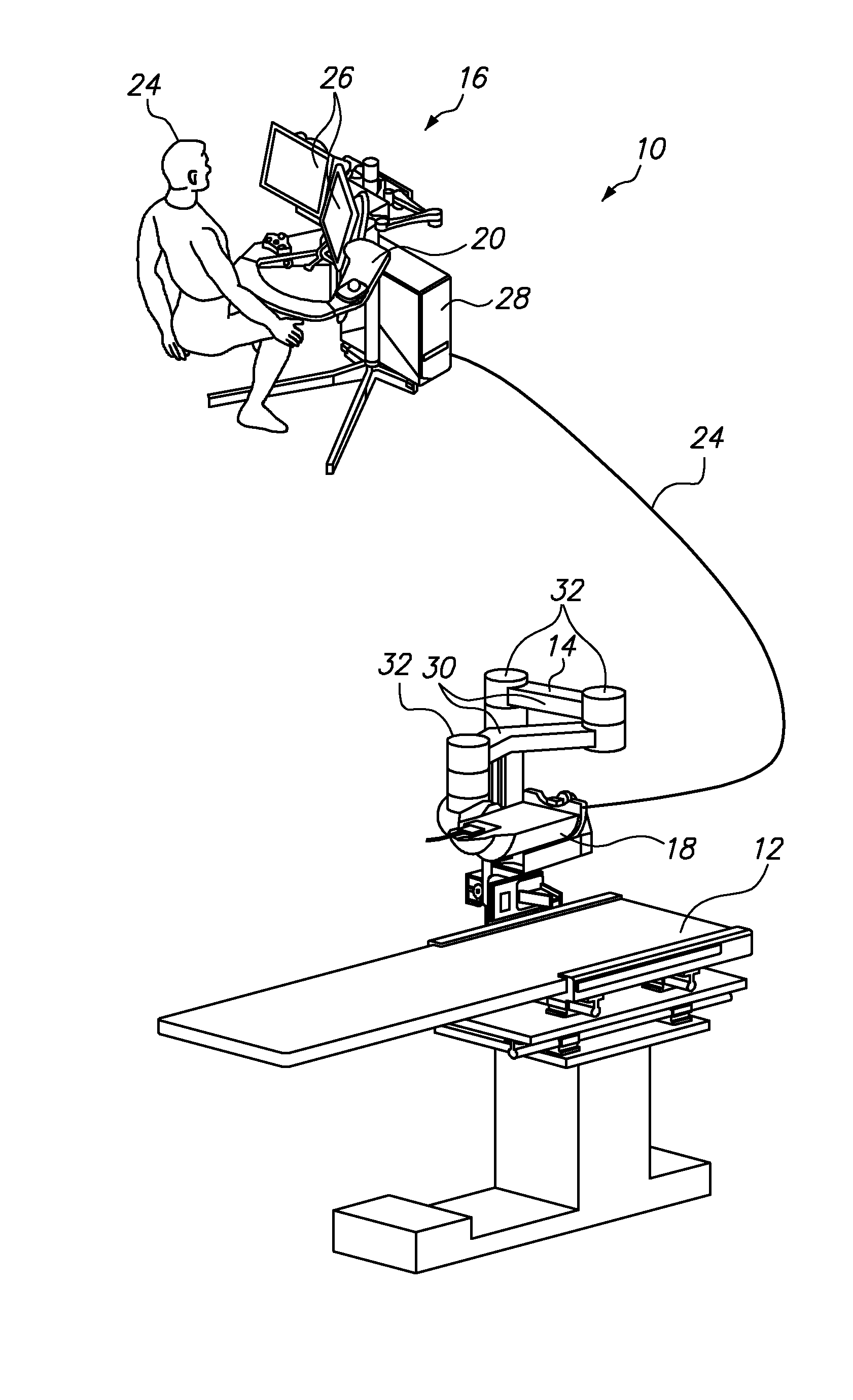
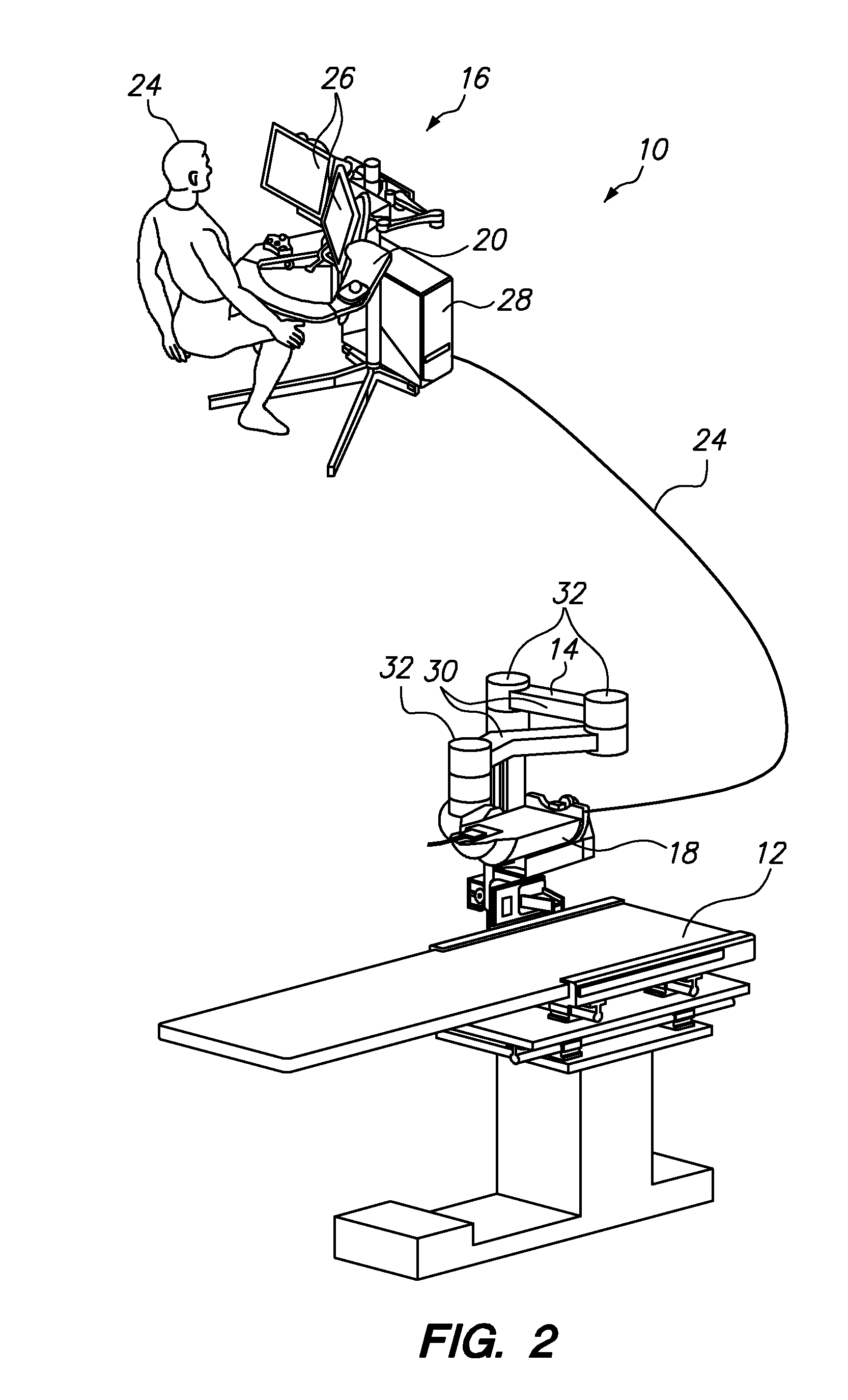
[0097]Referring to FIG. 2, one embodiment of a robotic catheter system 10 constructed in accordance with the present invention will now be described. The system 10 generally comprises an operating table 12 having a movable support-arm assembly 14, an operator control station 16 located remotely from the operating table 12, and a robotic catheter assembly 18 mounted to the support-arm assembly 14 above the operating table 12. Exemplary robotic catheter systems that may be modified for constructing and using embodiments of the present invention are disclosed in detail in the following U.S. patent applications, which are all expressly incorporated herein by reference in their entirety: U.S. patent application Ser. No. 11 / 678,001, filed Feb. 22, 2007; U.S. patent application Ser. No. 11 / 073,363, filed Mar. 4, 2005; U.S. patent application Ser. No. 11 / 179,007, filed Jul. 6, 2005; U.S. patent application Ser. No. 11 / 418,398, filed May 3, 2006; U.S. patent application Ser. No. 11 / 481,433, ...


PUM


Abstract

An instrument driver comprises a base and a jaw assembly coupled to the base. The jaw assembly includes a first jaw having a gripping surface and a second jaw having a gripping surface. The instrument driver further comprises a driver assembly operably coupled to the jaw assembly to advance an elongated member relative to the base by translating the first and second jaws toward each other, thereby closing the jaw assembly and gripping the member between the respective gripping surfaces of the first and second jaws, translating the jaw assembly in a first axial direction when the jaw assembly is closed, translating the first and second jaws away from each other, thereby opening the jaw assembly and releasing the member from between the respective gripping surfaces of the first and second jaws, and translating the jaw assembly in a second axial direction when the jaw assembly is opened.

Description

FIELD OF INVENTION[0001]The invention relates robotic catheter manipulators, and more particularly to drive mechanisms for inserting / retracting catheters in such robotic catheter manipulators.BACKGROUND[0002]Minimally invasive procedures are preferred over conventional techniques wherein the patient's body cavity is open to permit the surgeon's hands access to internal organs. Thus, there is a need for a highly controllable yet minimally sized system to facilitate imaging, diagnosis, and treatment of tissues which may lie deep within a patient, and which may be accessed via naturally-occurring pathways, such as blood vessels, other lumens, via surgically-created wounds of minimized size, or combinations thereof.[0003]Currently known minimally invasive procedures for the treatment of cardiac, vascular, and other disease conditions use manually or robotically actuated instruments, which may be inserted transcutaneously into body spaces such as the thorax or peritoneum, transcutaneousl...

Claims


Application Information

Patent Timeline
IPC IPC(8): A61B19/00A61F2/958
CPCA61B19/2203A61B2019/2211A61F2/95Y10S901/36A61B2017/00477A61B34/30A61B2034/301A61M25/0113A61B17/3403A61B2017/2924A61B2017/3409A61B17/3415A61M25/01A61M25/0105A61M2025/0175
Inventor LEWIS, PAUL E.YU, ALAN L.
Owner AURIS HEALTH INC
Why Eureka
Try Eureka