Device and a method for feeding a rocket engine propulsion chamber

a rocket engine and propulsion chamber technology, applied in the direction of machines/engines, vessel construction, marine propulsion, etc., can solve the problems of restricting the maximum pressure that can be reached, high pressure normally exists in the propulsion chamber, and restricting the specific impulse of the reaction engine, so as to avoid cavitation phenomena

Inactive Publication Date: 2014-09-25
SN DETUDE & DE CONSTR DE MOTEURS DAVIATION S N E C M A
View PDF0 Cites 10 Cited by
  • Summary
  • Abstract
  • Description
  • Claims
  • Application Information

AI Technical Summary

Benefits of technology

[0006]The present invention seeks to remedy those drawbacks. The invention seeks in particular to provide a feed device for feeding a rocket engine propulsion chamber with at least a first propellant, the device comprising at

Problems solved by technology

Consequently, high pressures normally exist in the propulsion chamber while it is in operation.
Nevertheless, that approach greatly restricts the maximum pressure that can be reached in the propulsion chamber and thus restricts the specific impulse of the reaction engine.
Nevertheless, both with pressurized tanks and with turbopumps it can be difficult to vary the flow rate of th

Method used


Image

  • Device and a method for feeding a rocket engine propulsion chamber
  • Device and a method for feeding a rocket engine propulsion chamber
  • Device and a method for feeding a rocket engine propulsion chamber

Examples


first embodiment

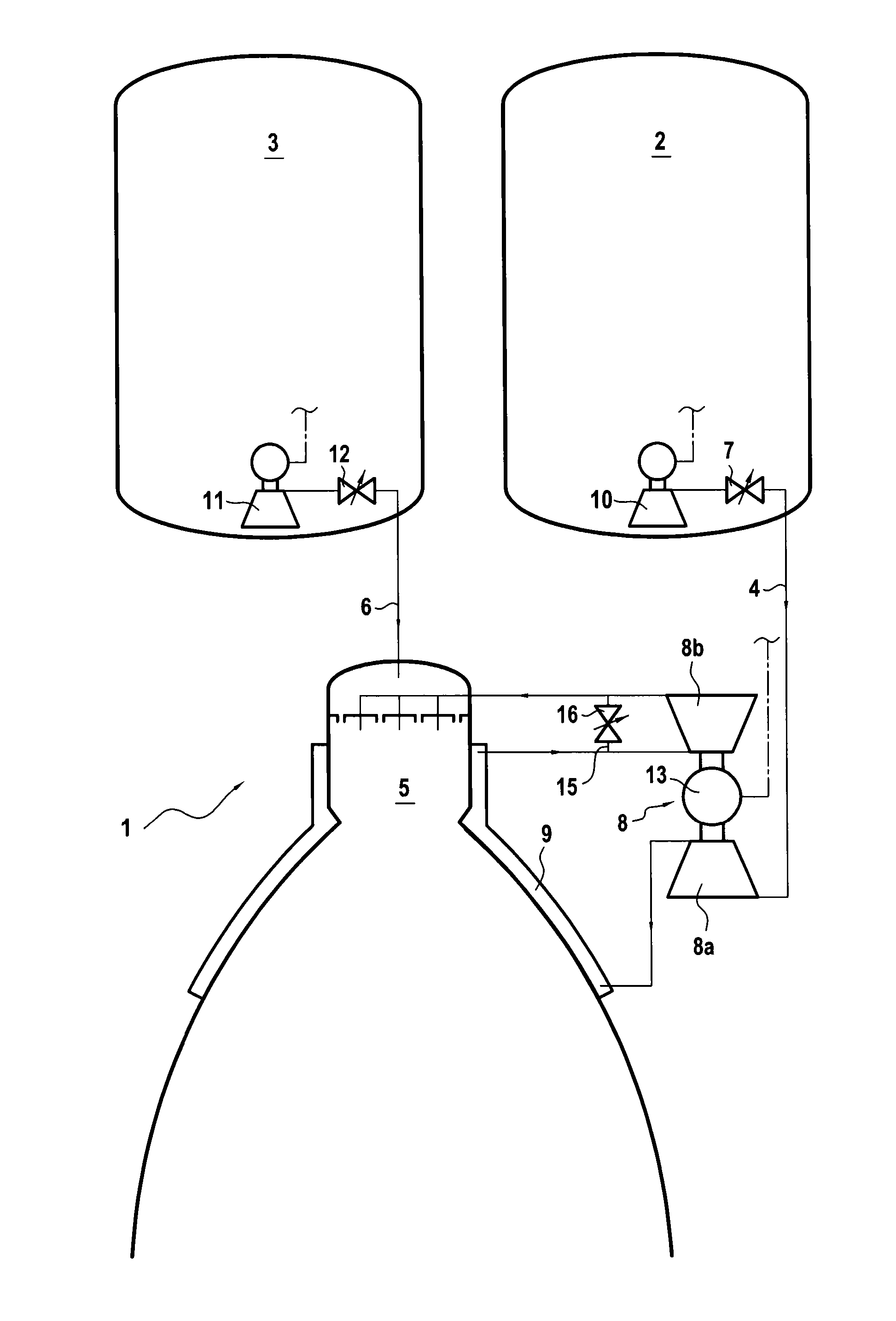
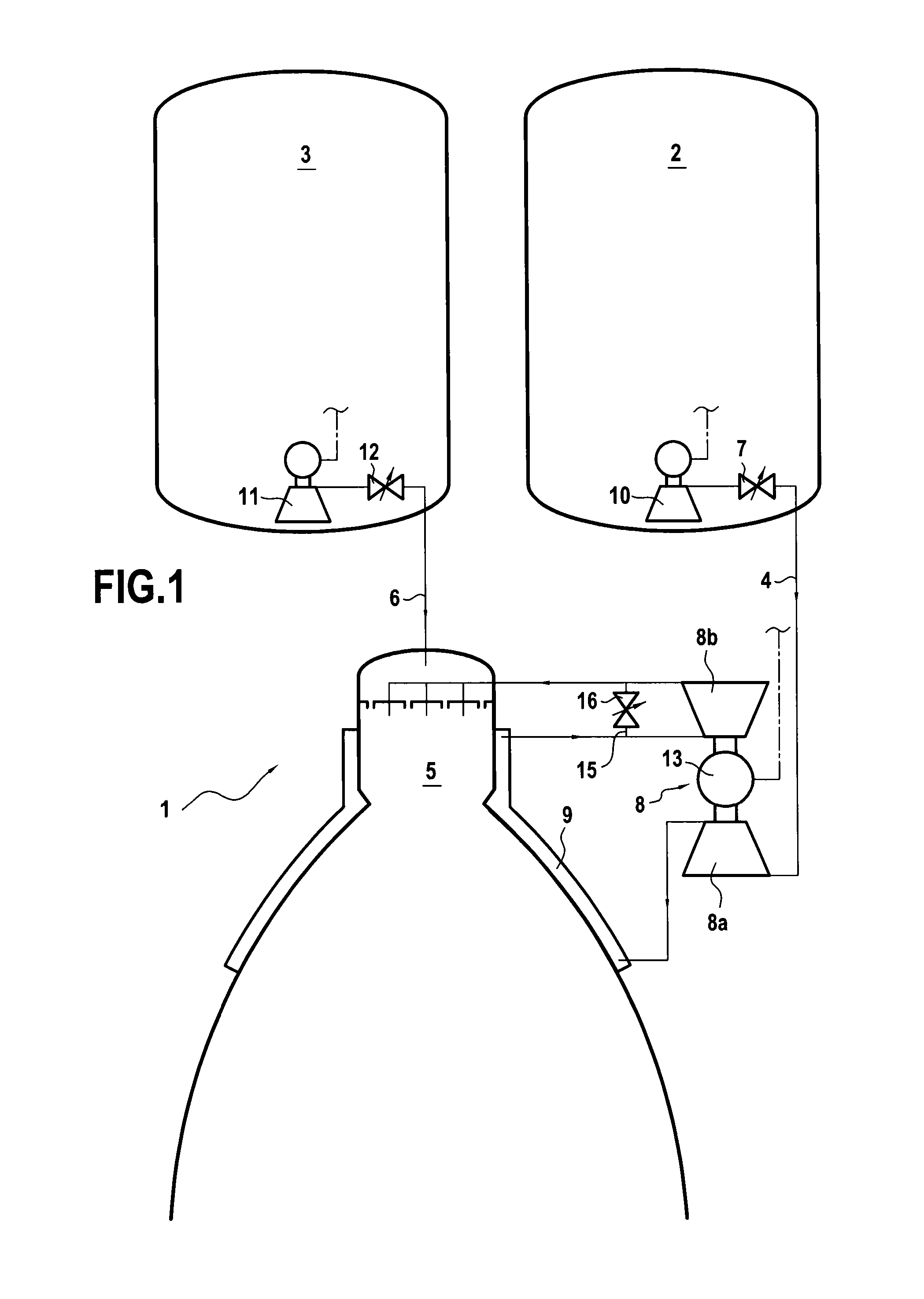
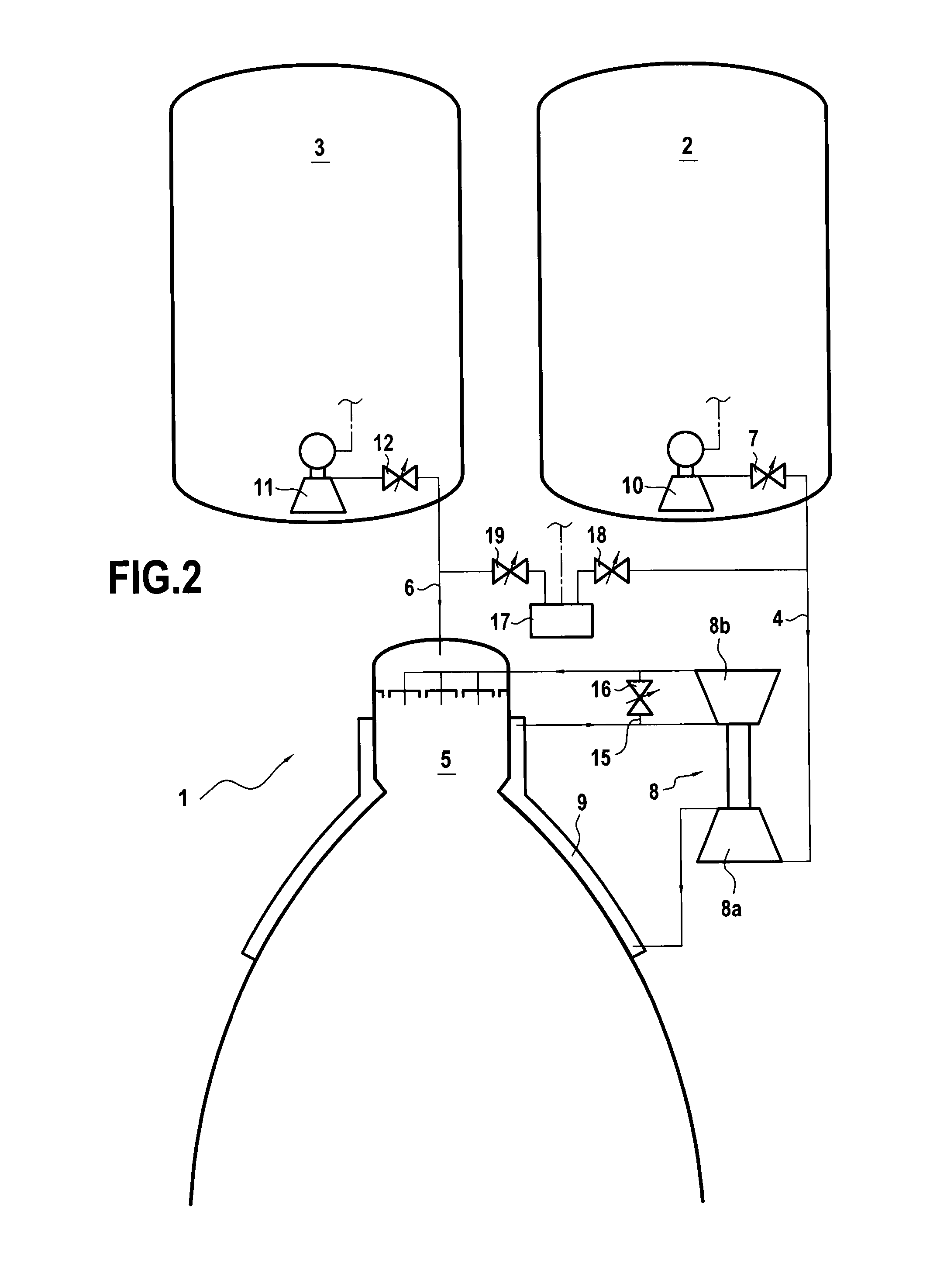
[0019]FIG. 1 shows a rocket engine 1 having a propulsion chamber 5 and a feed device for feeding the propulsion chamber with hydrogen and oxygen. The feed device comprises a tank 2 containing hydrogen in the liquid state, a tank 3 containing oxygen in the liquid state, a feed circuit 4 connected to the tank 2 to deliver hydrogen to the propulsion chamber 5 of the rocket engine 1, and a feed circuit 6 connected to the tank 3 to deliver oxygen to the propulsion chamber 5.

[0020]In addition, in this first embodiment, the hydrogen circuit 4 has an inlet valve 7, a turbopump 8 with a pump 8a and a turbine 8b that are mechanically coupled together, and a heat exchanger 9 formed in the walls of the propulsion chamber 5 in such a manner as to transfer heat from the propulsion chamber 5 to the hydrogen while it flows through the heat exchanger 9. The heat exchanger 9 is situated in the first circuit 4 downstream from the pump 8a and upstream from the turbine 8b. Thus, heat transfer in the hea...

fourth embodiment

[0032]The rocket engine 1′ shown in FIG. 4 has a propulsion chamber 5′ and a feed device for feeding the propulsion chamber with hydrogen and oxygen in a This feed device comprises a tank 2′ containing oxygen in the liquid state, a tank 3′ containing hydrogen in the liquid state, a feed circuit 4′ connected to the tank 2′ in order to deliver oxygen to the propulsion chamber5′ of the rocket engine 1′, and a feed circuit 6′ connected to the tank 3′ in order to deliver hydrogen to the propulsion chamber 5′.

[0033]Furthermore, in this fourth embodiment, the hydrogen circuit 6′ has an inlet valve 12′, a turbopump 8′ with a pump 8a′ and a turbine 8b′ that are mechanically coupled together, and a heat exchanger 9′ formed in the walls of the propulsion chamber 5′ so as to transfer heat from the propulsion chamber 5′ to the hydrogen while it is flowing through the heat exchanger 9′. The heat exchanger 9′ is situated in the circuit 6′ downstream from the pump 8a′ and upstream from the turbine...


PUM


Abstract

The invention relates to a device and a method for feeding a propulsion chamber 5 of a rocket engine 1 with at least with a first propellant. The device comprises at least a first tank 2 for containing said first propellant, a first feed circuit 4 connected to the first tank 2, and a first electric pump 10 within said first tank 2 in order to pump said first propellant through the first feed circuit 4. In the method, the first propellant is pumped through the first feed circuit 4 from the first tank 2 by at least said first electric pump 10 that is immersed in the first propellant within the first tank 2.

Description

BACKGROUND OF THE INVENTION[0001]The present invention relates to the field of feeding reaction engines and in particular it relates to a device and a method for feeding a propulsion chamber at least with a first propellant.[0002]In the description below, the terms “upstream” and “downstream” are defined relative to the normal flow direction of a propellant in a feed circuit.[0003]In reaction engines, and in particular in rocket engines, thrust is typically generated by hot combustion gas that is produced by an exothermal chemical reaction that has taken place within a propulsion chamber and that expands in a propulsion chamber nozzle. Consequently, high pressures normally exist in the propulsion chamber while it is in operation. In order to be able to continue to feed the combustion chamber in spite of those high pressures, propellants need to be introduced at pressures that are even higher. Various means are known in the prior art for achieving this.[0004]First means that have bee...

Claims


Application Information

Patent Timeline
IPC IPC(8): F02K9/44
CPCF02K9/46F02K9/44F02K9/605
Inventor SANNINO, JEAN MICHELEDELINE, EMMANUELHAYOUN, DAVID
Owner SN DETUDE & DE CONSTR DE MOTEURS DAVIATION S N E C M A
Why Eureka
Try Eureka