
Gas nozzle, plasma apparatus using the same, and method for manufacturing gas nozzle

a technology of plasma apparatus and gas nozzle, which is applied in the field of gas nozzle, plasma apparatus using the same, and method for manufacturing gas nozzle, which can solve the problems of particles falling off from the end surface, particles falling off from the surface, and damage to the surface of ceramic sintered bodies, etc., and achieve the effect of suppressing the fall of particles

Active Publication Date: 2014-09-25
KYOCERA CORP
View PDF5 Cites 17 Cited by
  • Summary
  • Abstract
  • Description
  • Claims
  • Application Information

AI Technical Summary

Benefits of technology

The gas nozzle described in this patent can prevent particles from falling off. The manufacturing method for this nozzle can create it without any particles falling off.

Problems solved by technology

However, when a ceramic sintered body is used for the gas nozzle, although grinding processing and / or polishing processing is required to obtain a desired shape, the surface of the ceramic sintered body is damaged by the processing as described above, and hence particles are liable to fall off from the surface.
In addition, when the film formation apparatus or the etching apparatus is used, an end surface having a raw material-gas exhaust port of the gas nozzle is exposed to a gas in a reaction chamber and is damaged thereby, so that particles are liable to fall off from the end surface.
When the particles are adhered to a substrate, defects are liable to be generated on the substrate in some cases.

Method used


Image

  • Gas nozzle, plasma apparatus using the same, and method for manufacturing gas nozzle
  • Gas nozzle, plasma apparatus using the same, and method for manufacturing gas nozzle
  • Gas nozzle, plasma apparatus using the same, and method for manufacturing gas nozzle

Examples


examples

[0051]Hereinafter, although the present invention will be described in detail with reference to examples, the present invention is not limited to the following examples, and changes and embodiments, which are within the scope of the present invention, are both within the range of the present invention.

[0052](Evaluation Method)

[0053]As shown in Table 1, after gas nozzles of Samples 1 to 15 were formed using various types of ceramic sintered bodies and processing methods, the surfaces of the gas nozzles were each observed by a digital microscope device manufactured by Keyence Corporation, so that the average crystalline grain diameter (D) of one end surface of a main body was measured. In addition, the surface condition of each gas nozzle was measured by a surface roughness meter manufactured by Kosaka Laboratory Ltd., so that the mean width of the profile elements (Rsm) and the arithmetic average roughness (Ra) of the one end surface of the main body were measured. In addition, plasm...


PUM

PropertyMeasurementUnit
arithmetic average roughnessaaaaaaaaaa
Raaaaaaaaaaa
temperatureaaaaaaaaaa

Abstract

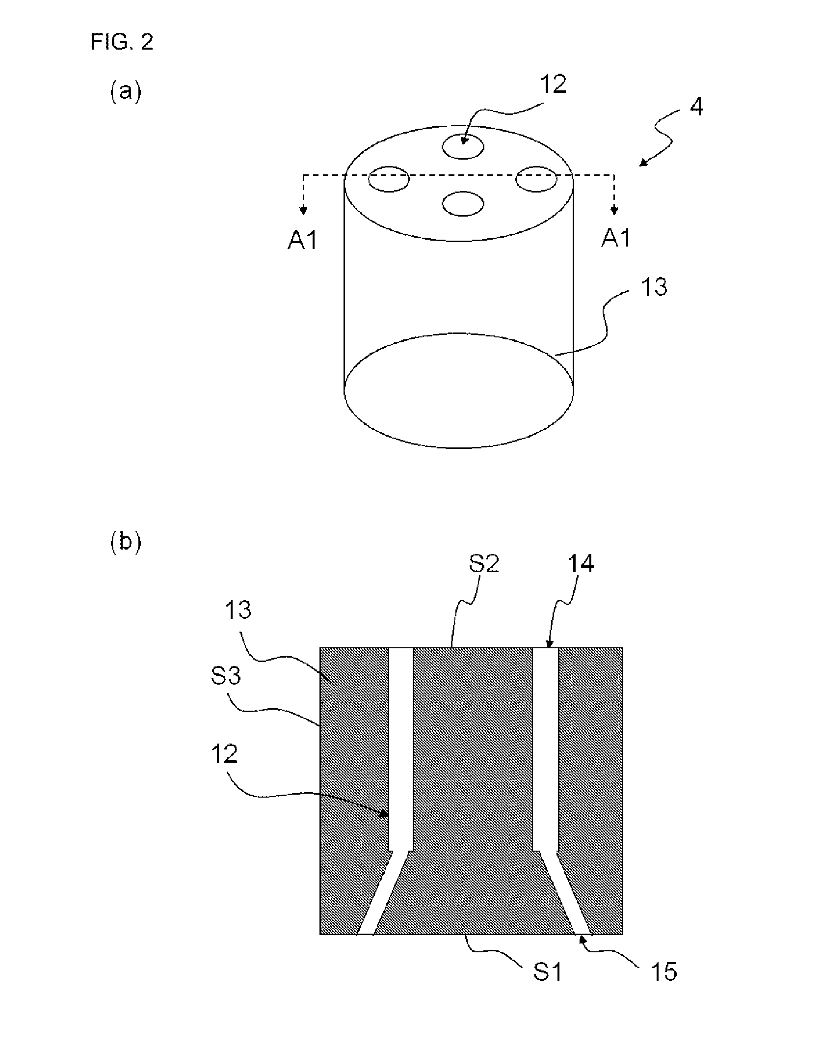
[Object] To provide a gas nozzle which meets a requirement to suppress the fall of particles.[Solution] A gas nozzle 4 according to an aspect of the present invention includes a columnar main body 13 formed of a ceramic sintered body provided with a through-hole 12 formed therein through which a gas flows, an exhaust port 15 of the through-hole 12 for the gas is formed in one end surface S1 of the main body 13, and the mean width of the profile elements (Rsm) of the one end surface S1 is 5 times or more the average crystalline grain diameter of the ceramic sintered body.

Description

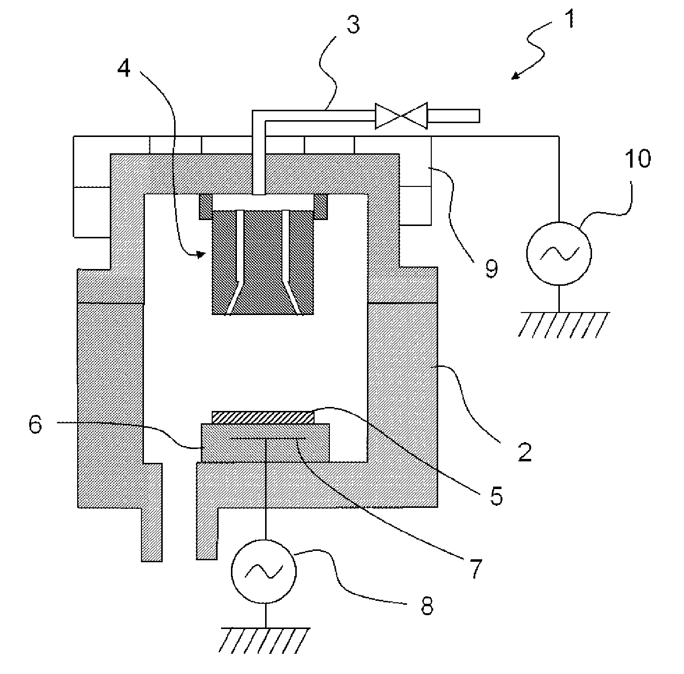
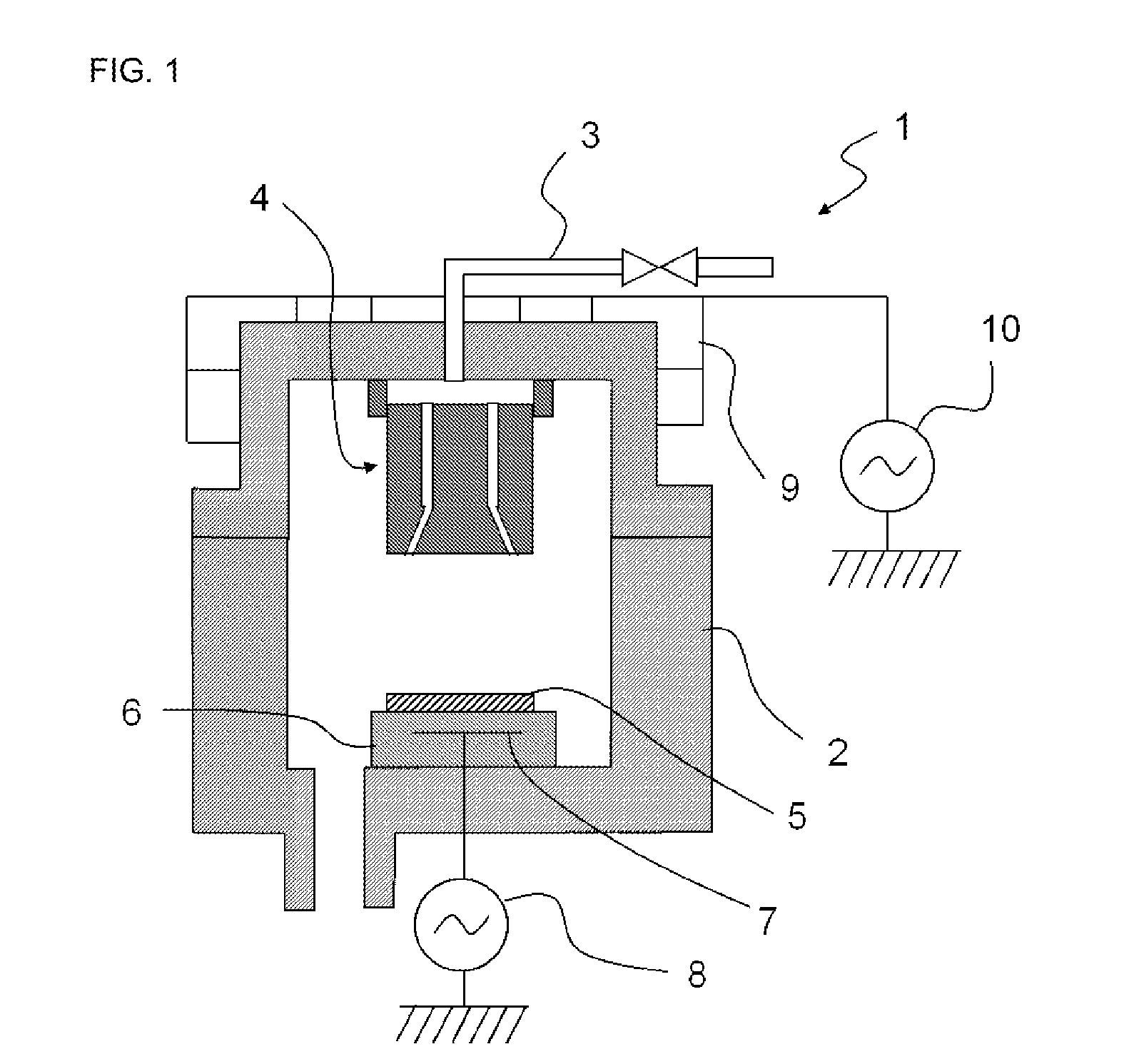
TECHNICAL FIELD[0001]The present invention relates to a gas nozzle used for a plasma apparatus, such as a film formation apparatus or an etching apparatus, for manufacturing semiconductor or liquid crystal devices, a plasma apparatus using this gas nozzle, and a method for manufacturing a gas nozzle.BACKGROUND ART[0002]Heretofore, in a semiconductor or a liquid crystal manufacturing process, there have been used plasma apparatuses including a film formation apparatus to form a thin film on a substrate, such as a semiconductor wafer or a glass substrate, and an etching apparatus to perform microprocessing on a substrate. In the film formation apparatus, a raw material gas is steadily supplied and introduced into a reaction chamber and is then subjected to a chemical reaction, so that a thin film is formed on a substrate. In addition, in the etching apparatus, a halogenated corrosive gas is introduced therein as a raw material gas and is then plasmatized to be used as an etching gas, ...

Claims


Application Information

Patent Timeline
Patent Type & Authority Applications(United States)
IPC IPC(8): H01J37/32B24B37/00
CPCB24B37/00H01J37/3244B24B37/04C04B35/03C04B35/44C04B35/443C04B35/505C04B35/6261C04B35/62645C04B35/62655C04B35/62695C04B2235/3206C04B2235/3208C04B2235/3217C04B2235/3244C04B2235/3418C04B2235/5436C04B2235/786C04B2235/94C04B2235/963C04B2235/9669C23C16/4404C23C16/45563
Inventor TANAKA, ATSUSHI
Owner KYOCERA CORP
Learn More