Touch-control method for liquid display device and touch-controllable liquid crystal display device

a liquid crystal display and touch control technology, applied in the field of display techniques, can solve the problems of deteriorating display effect, light transmittance, deteriorating display effect, etc., and achieve the effect of reducing light transmittance and display area, and not increasing the thickness and weight of the liquid crystal display

Active Publication Date: 2014-09-25
FOCALTECH ELECTRONICS
View PDF4 Cites 11 Cited by
  • Summary
  • Abstract
  • Description
  • Claims
  • Application Information

AI Technical Summary

Benefits of technology

[0011]In the embodiments of the invention, a design conception in which the electrodes already present the liquid crystal display are used in a time division multiplex way is applied, so that the liquid crystal display device may switch between the display mode and the touch-control mode. In the display mode, the liquid crystal display device displays normally. In the touch-control mode, the common electrode or the signal electrode that the liquid crystal display device

Problems solved by technology

Moreover, the touch panel may affect the light transmittance and deteriorate the display effect.
However,

Method used


Image

  • Touch-control method for liquid display device and touch-controllable liquid crystal display device
  • Touch-control method for liquid display device and touch-controllable liquid crystal display device
  • Touch-control method for liquid display device and touch-controllable liquid crystal display device

Examples


first embodiment

[0031]Referring to FIG. 5, an embodiment of the invention provides a touch-control method for a liquid crystal display device, including Steps 101 to 106.

[0032]Step 101: switching from a display mode to a touch-control mode.

[0033]In the embodiment of the invention, a design conception in which the electrodes already present in the liquid crystal display are used in a time division multiplex way is employed, so that the liquid crystal display device may have two operation modes, i.e. a display mode and a touch-control mode, one of which can be switched to the other. The liquid crystal display device operates in the display mode after being turned on. Triggered by a preset event, the liquid crystal display device may switch from the display mode to the touch-control mode as required. At the end of the touch or being triggered by a preset event, the liquid crystal display device may switch back to the display mode. The preset event may be an event in which a special button is pressed, ...

second embodiment

[0061]Referring to FIG. 17, an embodiment of the invention provides a touch-controllable liquid crystal display device including a display portion 210 and a touch-control portion 220.

[0062]As shown in FIGS. 6 to 8, the display portion includes a thin film transistor (TFT) and a switching electrode for the TFT, a signal electrode and a drain electrode which are connected to the TFT, a pixel electrode connected to the drain electrode, a common electrode for forming an electric field with the pixel electrode to control whether to display an image, and so on.

[0063]As shown in FIG. 17, the touch-control portion 220 may be a touch-control processor connected to the signal electrode and the common electrode. The touch-control processor may include:

[0064]a switching unit 2201 configured to switch between a display mode and a touch-control mode;

[0065]a starting unit 2202 configured to, in the touch-control mode, determine whether there is a touch made by an object or whether there is an inpu...


PUM


Abstract

A touch-control method for a liquid crystal display device, includes: switching from a display mode to a touch-control mode; determining whether there is a touch made by an object or whether there is an input made by an active pen; in the case where there is the input made by the active pen, starting an active pen detecting sub-mode in which an X-axis direction common electrode of the liquid crystal display device is defined as an X-axis direction receiving electrode, and a Y-axis direction common electrode or a signal electrode is defined as a Y-axis direction receiving electrode; and determining a position or an action of the active pen according to amplitudes of signals of the X-axis direction receiving electrode and the Y-axis direction receiving electrode. A touch-controllable liquid crystal display device is further provided.

Description

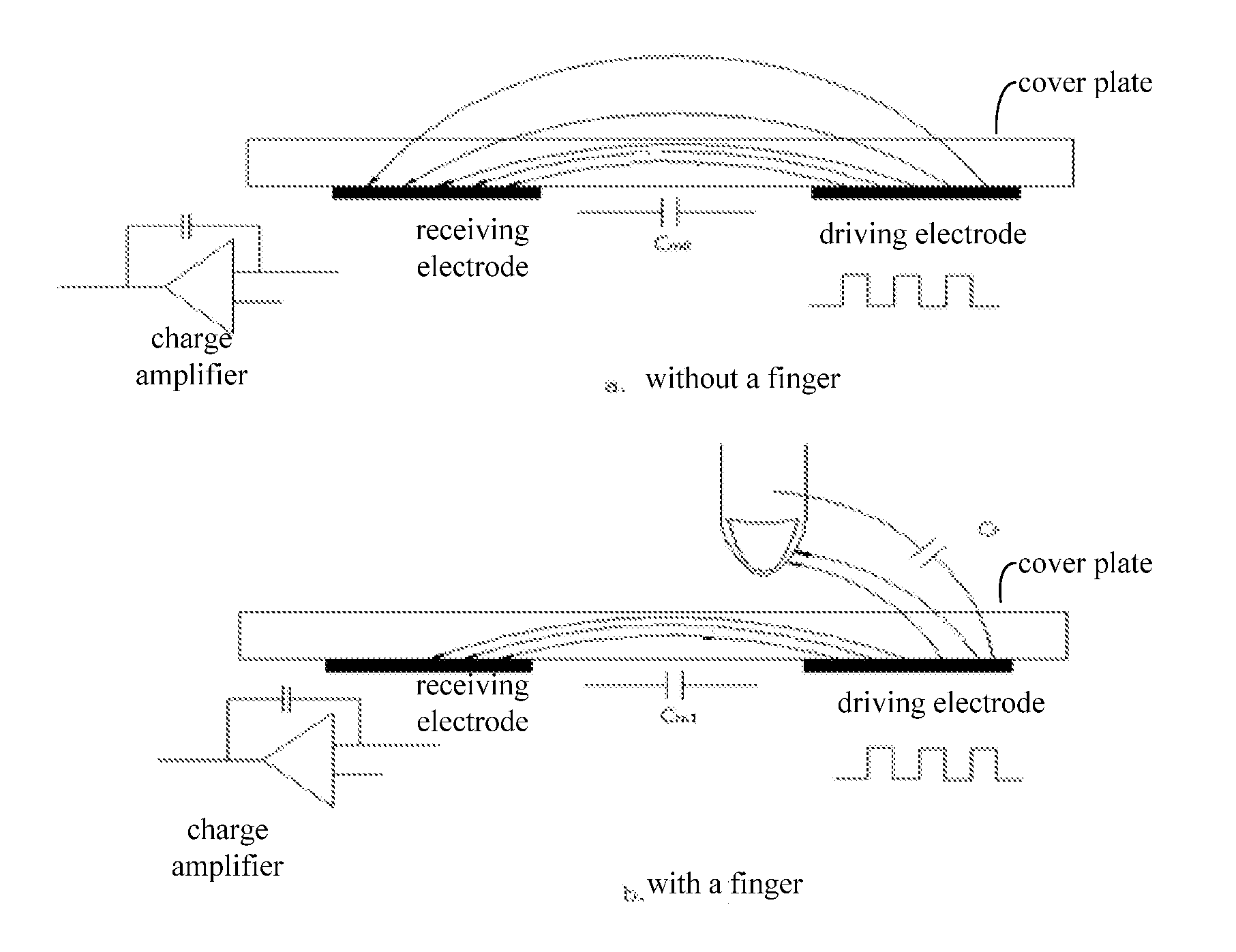
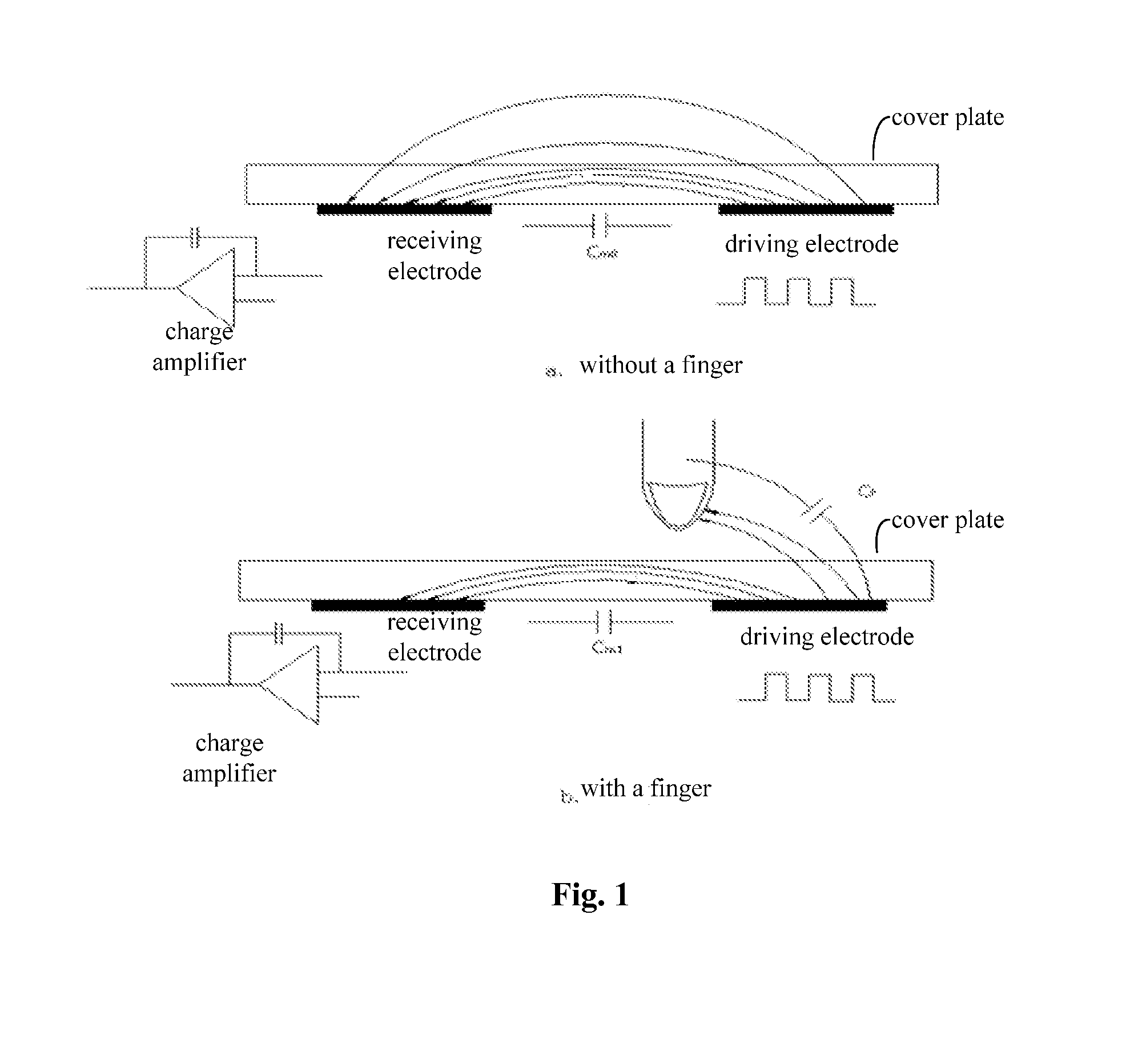
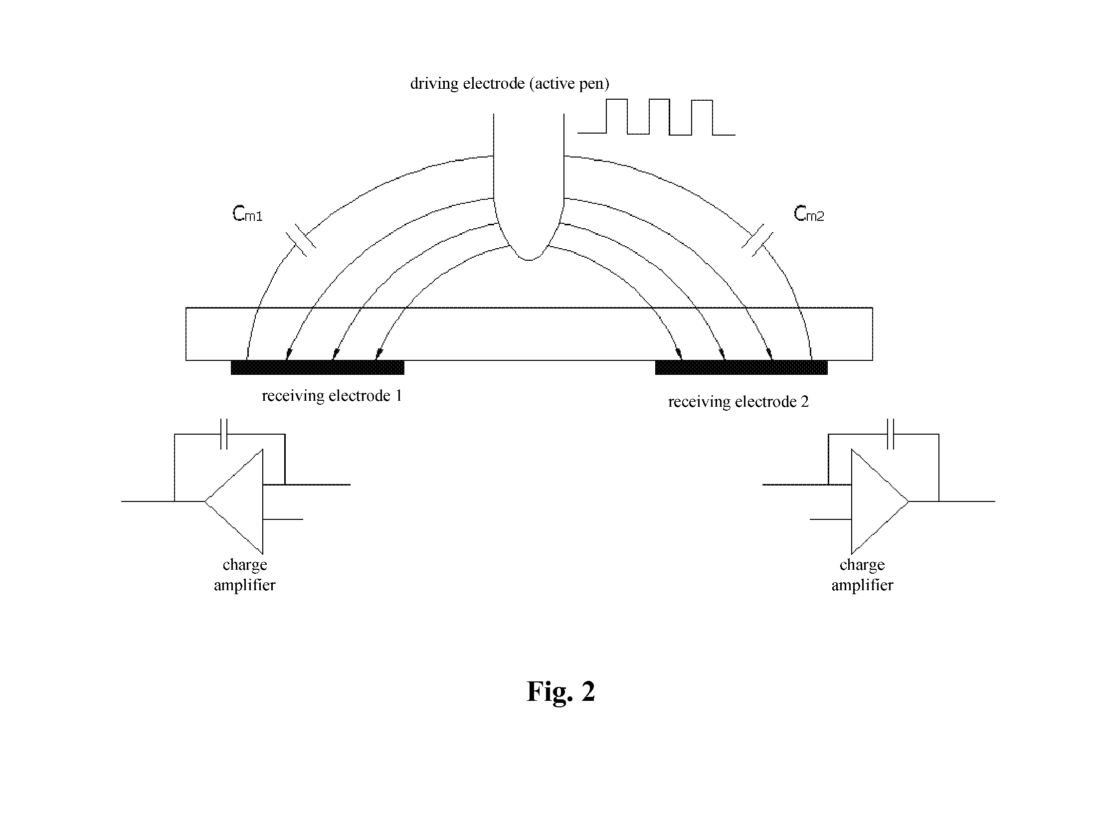
CROSS REFERENCE TO RELATED APPLICATION[0001]This application claims the benefit of priority to Chinese Patent Application No.201310090330.X, entitled “TOUCH-CONTROL METHOD FOR LIQUID DISPLAY DEVICE AND TOUCH-CONTROLLABLE LIQUID CRYSTAL DISPLAY DEVICE”, filed on Mar. 30, 2013 with State Intellectual Property Office of PRC, which is incorporated herein by reference in its entirety.FIELD OF THE INVENTION[0002]The present invention generally relates to the field of display technique, and in particular to a touch-control method for a liquid crystal display device and a touch-controllable liquid crystal display device.BACKGROUND OF THE INVENTION[0003]Currently, there are the following common touch-control technologies.[0004]One touch-control technology is mutual capacitance touch sensing technology. As shown in FIG. 1, a touch is determined based on the mutual capacitance by detecting a coupling capacitance between a driving electrode and a receiving electrode. In the case where there is ...

Claims


Application Information

Patent Timeline
IPC IPC(8): G06F3/044
CPCG06F3/044G06F3/03545G06F3/0412G09G3/3648G09G2354/00G06F3/04166G06F3/0442G06F3/0446G06F3/00G06F3/0416
Inventor MO, LIANGHUAJIANG, XINXILI, HUAWANG, PENG
Owner FOCALTECH ELECTRONICS
Why Eureka
Try Eureka