

Projection apparatus, projection method, and projection program medium
a projection apparatus and projection method technology, applied in the direction of projectors, color television details, instruments, etc., can solve the problems of inflexible distortion correction and image distortion, and achieve the effect of increasing the flexibility of distortion correction
- Summary
- Abstract
- Description
- Claims
- Application Information
AI Technical Summary
Benefits of technology
Problems solved by technology
Method used
Image

Examples
first embodiment
[0046]A first embodiment will be described with reference to the drawings.
[0047]A projection apparatus according to the present embodiment employs digital light processing (DLP) (registered trademark) using a micromirror display device as an output display device.
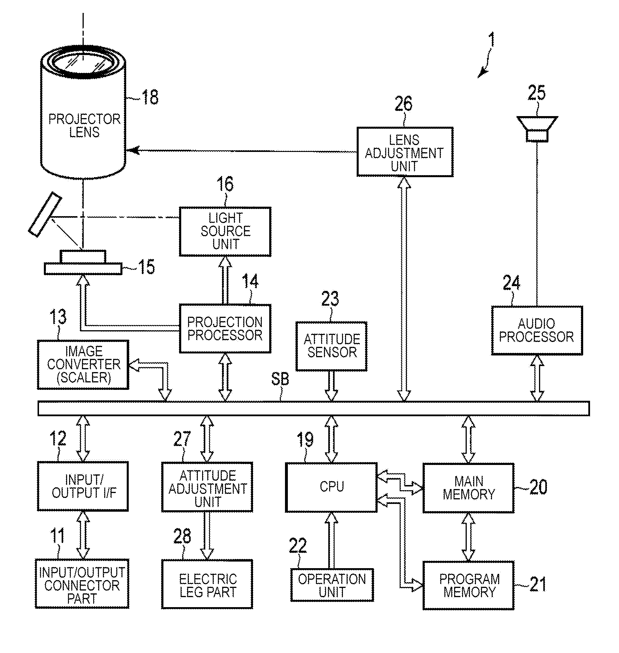
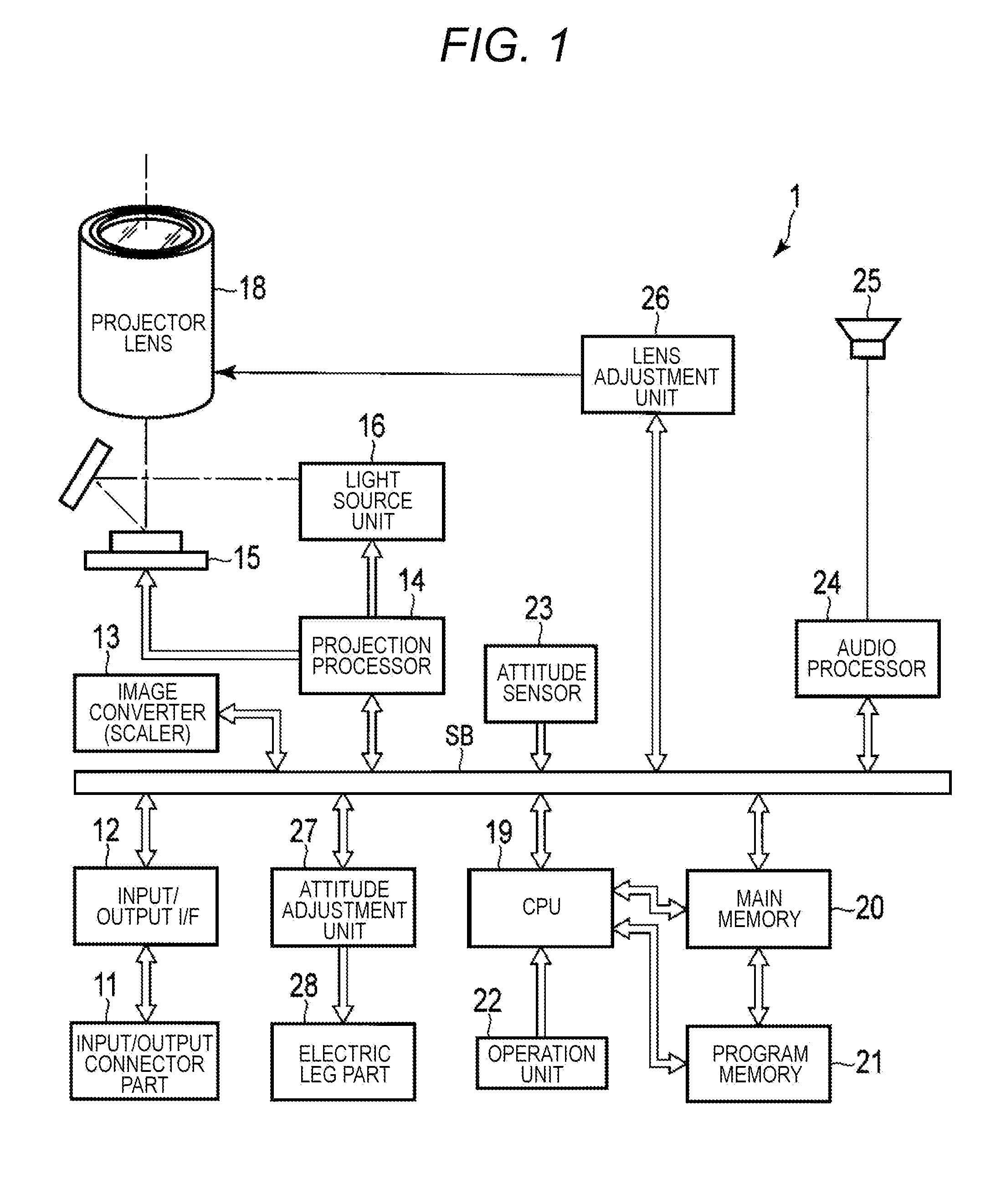
[0048]FIG. 1 illustrates an outline of a configuration of a projector 1 that is a projection apparatus according to the present embodiment. The projector 1 includes an input / output connector part 11, an input / output interface (I / F) 12, an image converter 13, a projection processor 14, a micromirror device 15, a light source unit 16, a mirror 17, a projector lens 18, a CPU 19, a main memory 20, a program memory 21, an operation unit 22, an attitude sensor 23, an audio processor 24, a speaker 25, a lens adjustment unit 26, an attitude adjustment unit 27, an electric leg part 28, and a system bus SB.
[0049]The input / output connector part 11 is provided with terminals such as a pin-jack (RCA) video input terminal and a D-sub 15 ...
second embodiment
[0134]A second embodiment will be described. In the second embodiment, differences from the first embodiment will be described, and parts that are the same as those in the first embodiment will be designated by the same reference numerals and the description thereof will not be repeated.
[0135]In the present embodiment, the roll angle can also be adjusted in distortion correction so as to further improve the pixel usage.
[0136]The electric leg part 28 for supporting the housing of the projector 1 thus functions as an attitude and roll adjustment mechanism to change the attitude and the roll angle of the projector 1. Specifically, as illustrated in FIG. 6, the electric leg part 28 can adjust the levelness of the projector 1 by changing the length of each leg 28A independently, and / or adjust the roll angle without changing the optical axis direction (projecting direction) of the projector optical system, that is, by rotating the projector 1 about the optical axis.
[0137]The roll angle wi...
modified example
[0173]While the roll angle is changed by using the electric leg part 28 in the second embodiment, the roll angle changing mechanism is not limited thereto.
[0174]For example, as illustrated in FIG. 12, it may be considered to use a roll base 31 including a tiltable plate 29 and a rotatable plate 30. Specifically, the projector 1 is placed on the rotatable plate 30 provided on the tiltable plate 29. In FIG. 12, p represents an angle of rotation (the angle in the yaw direction) of the rotatable plate 30, and q represents an angle of inclination (the angle in the pitch direction) of the tiltable plate 29. These p and q correspond to p and q, respectively, in the formula (1). In this case, the roll angle can be automatically applied, and control and drive for changing the roll angle are thus unnecessary. Note that, in FIG. 12, the screen is placed in a manner that the z axis of the projector coordinate system is perpendicular to the screen when p=q=0.
[0175]Thus, the projector coordinate ...
PUM
 Abstract
Description
Claims
Application Information