Electronic compensation of cross-phase modulation

a cross-phase modulation and electronic compensation technology, applied in the direction of fibre transmission, distortion/dispersion elimination, electrical equipment, etc., can solve the problem that the channel capacity limitation of a coherent optical communication link is generally nonlinear transmission impairment, the channel capacity of an optical link cannot be increased indefinitely, and the degradation of transmitted signals. to achieve the effect of maximising the quality of the compensated signal

Active Publication Date: 2014-09-25
OFIDIUM PTY LTD
View PDF13 Cites 16 Cited by
  • Summary
  • Abstract
  • Description
  • Claims
  • Application Information

AI Technical Summary

Benefits of technology

[0043]wherein the predetermined characteristic of the filter is represented by one or more parameters

Problems solved by technology

As a result, the ultimate limitation on channel capacity within a coherent optical communications link is generally the nonlinear transmission impairments.
Degradation of transmitted signals due to fibre nonlinearity increases with transmission power, and accordingly the channel capacity of an optical link cannot be increased indefinitely merely by increasing the signal launch power.
However, compensating for fibre nonlinearity is challenging in the presence of CD, because the intensity waveform evolves along each fibre span.
However, dispersion-managed systems can create their own problems when used to carry coherent optical channels, due to the impact of dispersion management on the nonlinear impairments.
For example, c

Method used


Image

  • Electronic compensation of cross-phase modulation
  • Electronic compensation of cross-phase modulation
  • Electronic compensation of cross-phase modulation

Examples


Embodiment Construction

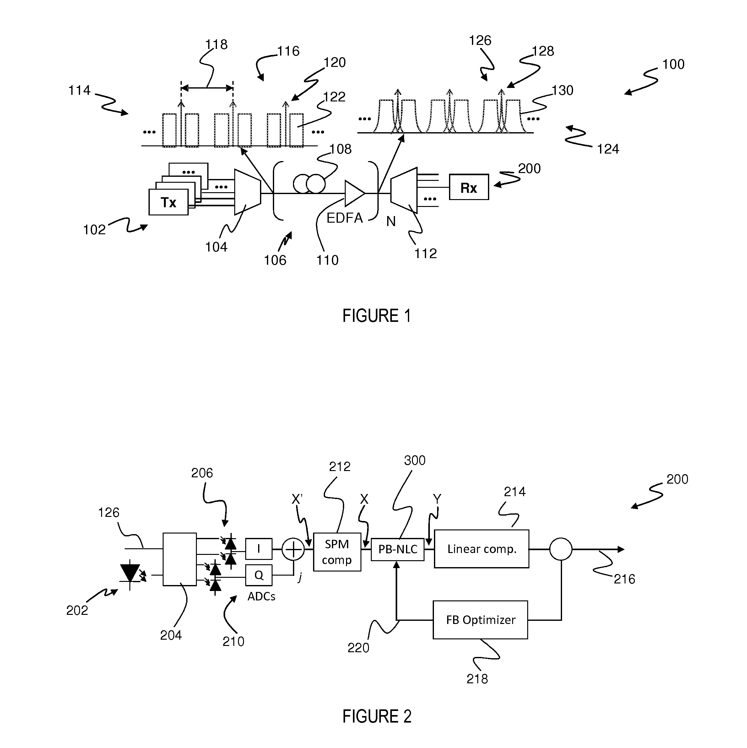
[0053]FIG. 1 is a schematic diagram of an optical transmission system 100 embodying the present invention. The system 100 employs Wavelength Division Multiplexing (WDM), in which a plurality of transmitters 102, each operating at a different wavelength, are multiplexed via a WDM multiplexer 104, and the resulting WDM signal is transmitted via optical transmission link 106. The link 106 comprises a plurality (N) of spans, each of which includes a length of single-mode optical fibre 108, and an amplifier 110, such as an Erbium-Doped Fibre Amplifier (EDFA). Some or all of the fibre spans may also incorporate chromatic dispersion management or compensation elements, such as dispersion compensating fibres, which may advantageously be deployed within the amplifying modules 110.

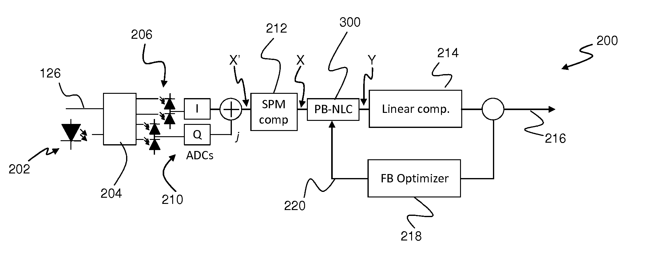
[0054]A WDM demultiplexer 112 separates the various transmitted wavelength channels, each of which is received via a receiver 200 embodying the present invention.

[0055]The optical transmission link 106 has an input ...


PUM


Abstract

An optical signal (116) is modulated with a transmitted electrical signal comprising an information-bearing component (122) and a pilot tone (120) having a predetermined frequency. Transmission of the signal results in distortion, including nonlinear optical transmission impairments. A method of receiving the signal includes detecting the optical signal to produce a received electrical signal (X) comprising a distorted variant of the transmitted electrical signal. The pilot tone is extracted from the received electrical signal using a filtering operation (308) having a predetermined characteristic, and a compensation signal determined based upon the extracted pilot tone. The compensation signal is applied to the received electrical signal (X) to produce a compensated signal (Y) having reduced distortion. The predetermined characteristic of the filtering operation (308) is represented by one or more parameters having values selected so as to substantially maximise a measure of quality of the compensated signal.

Description

FIELD OF THE INVENTION[0001]The present invention relates to coherent optical communications, and in particular a method, apparatus and system for mitigation of nonlinear transmission impairments.BACKGROUND OF THE INVENTION[0002]In recent times, there has been an increasing interest in the use of coherent optical communications for high-capacity and long-haul transmission, particularly at bit rates of 40 Gb / s and higher.[0003]Coherent optical communication systems provide a number of potential advantages over more-conventionally deployed incoherent (i.e. intensity-modulated direct-detection) systems. These include improved receiver sensitivity, the ability to employ more sophisticated and spectrally efficient modulation formats, and the ability to compensate for linear transmission impairments, such as Chromatic Dispersion (CD) and Polarisation Mode Dispersion (PMD), within the electronic domain, for example using digital signal processing within the optical receiver.[0004]As a resu...

Claims


Application Information

Patent Timeline
IPC IPC(8): H04B10/69H04B10/61
CPCH04B10/616H04B10/2507H04B10/697H04B10/6971
Inventor LOWERY, ARTHUR JAMESDU, LIANG BANGYUAN
Owner OFIDIUM PTY LTD
Why Eureka
Try Eureka