Supercharge Your Innovation With Domain-Expert AI Agents!

Circuit Breaker With Fluid Injection

a circuit breaker and fluid injection technology, applied in the field of high-voltage technology, can solve the problems that neither electrical means, such as electrical power supplies, nor external mechanical components are needed to pressurize, and achieve the effects of improving the performance of background gas, high dielectric strength, and high dielectric strength

Active Publication Date: 2014-10-02
HITACHI ENERGY SWITZERLAND AG
View PDF2 Cites 9 Cited by
  • Summary
  • Abstract
  • Description
  • Claims
  • Application Information

AI Technical Summary

Benefits of technology

The patent is about a device used to prevent damage from electrical arbritage in circuit breakers. The device uses a liquid called a fluoroketone that is vaporized using the electrical energy of the arbitrage to extinguish the flame. The device is designed to be simple and cost-effective, as it doesn't require high pressure or external components to operate. Additionally, the device uses a background gas, such as CO2 or N2, to improve its insulation performance. The fluoroketone liquid used in the device also cools the exhaust gases efficiently after it has been ejected. Overall, this patent provides a solution for preventing electrical aravelage damage in a simple, cost-effective way.

Problems solved by technology

In particular, neither electrical means, such as an electrical power supply, nor external mechanical components are needed to pressurize and eject the arc-extinction medium.

Method used


Image

  • Circuit Breaker With Fluid Injection
  • Circuit Breaker With Fluid Injection
  • Circuit Breaker With Fluid Injection

Examples


first embodiment

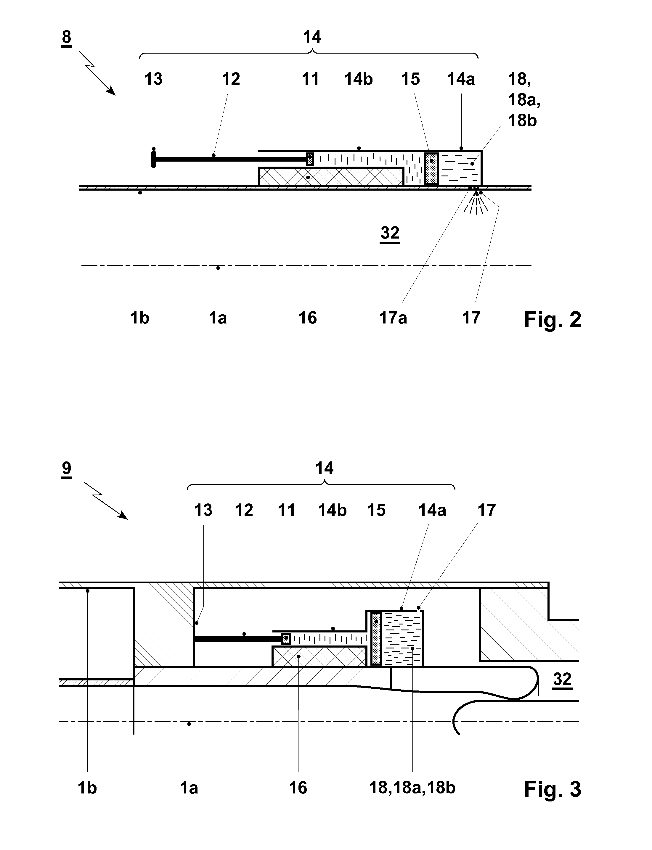
[0075]FIG. 2 shows an outside ejection device 8 with a compression mechanism 14 comprising a compartment 14a for arc-extinction medium 18; 18a, 18b, in particular arc-extinction liquid 18; 18a, 18b. The arc-extinction medium 18; 18a, 18b contained in compartment 14a comprises or is for example an organofluorine compound having a boiling point Tb at 1 bar higher than −60° C.

[0076]The ejection device further comprises an auxiliary compartment 14b separated from and mechanically connected to the compartment 14a by a floating piston 15, and a mechanically driven piston 11 of the auxiliary compartment 14b. The compression mechanism 14 according to FIG. 2 is arranged outside the circuit breaker enclosure 1b. The compartment 14a serves for receiving, storing and ejecting the arc-extinction medium 18; 18a, 18b under pressure. As shown, the piston 11 can e.g. be fixedly supported on a wall 13 while the compression mechanism 14, in particular the auxiliary compartment 14b, is moveable, typica...

second embodiment

[0078]FIG. 3 shows an inside ejection device 9 with a compression mechanism 14 comprising a compartment 14a for the arc-extinction medium 18; 18a, 18b, in particular the arc-extinction liquid 18; 18a, 18b, an auxiliary compartment 14b separated from and mechanically connected to the compartment 14a by a floating piston 15, and a mechanically driven piston 11 of the auxiliary compartment 14b. The ejection device 9 and in particular the compression mechanism 14 is now arranged inside the circuit breaker enclosure 1b. The functions of the elements, in particular the moveable mechanism 14, the preferably fixed piston 11, the liquid compartment 14a and the auxiliary compartment 14b are as described above for FIG. 1.

[0079]In both embodiments of FIGS. 1 and 2, the pressure in the compartment 14a filled with the incompressible arc-extinction medium 18; 18a, 18b, typically a liquid 18; 18a, 18b, is increased by the compressive force exerted onto the interior of the compartment 14a via the ex...


PUM


Abstract

A circuit breaker including an ejection device with a compartment, in which an arc-extinction medium for improving circuit breaker operation is contained, and having an ejection orifice through which the arc-extinction medium is to be ejected, wherein the ejection orifice opens out into an injection zone of the circuit breaker in which the pressure is lower than in an arcing zone when an arc is present, and wherein the arc-extinction medium and / or exhaust-cooling medium is at least partially present in liquid form, when it is contained in the ejection device.

Description

FIELD OF THE INVENTION[0001]The present invention relates to the field of high-voltage technology, and more specifically to a circuit breaker, to a switchgear, and to a method for improved circuit breaker operation.BACKGROUND OF THE INVENTION[0002]In conventional circuit breakers, the arc formed during a breaking operation is normally extinguished using compressed gas. The arc extinction or interruption performance is thereby mostly defined by the blow pressure and the physical properties of the medium, e.g. the dielectric strength, the heat capacity as a function of temperature, the electronegativity and the thermal conductivity. For large ratings, compressed sulphur hexafluoride (SF6) is generally used.[0003]Typically, the arc interruption performance is improved by increasing the blow pressure of the gas using the self-blast or puffer principle. Although up to a certain rating the required interruption performance can be achieved, compressed-gas circuit breakers have intrinsic li...

Claims


Application Information

Patent Timeline
Patent Type & Authority Applications(United States)
IPC IPC(8): H01H33/22
CPCH01H33/22H01H33/90H01H33/901H01H33/903H01H33/60H01H33/95H01H2033/908H01H2033/912H01H33/91
Inventor PISU, FRANCESCOGALINDO-LOZANO, FRANCIAMANTILLA, JAVIERBUERGLER, MATHIAS-DOMINICGARIBOLDI, NICOLACOSSALTER, OLIVERSTOLLER, PATRICKGROB, STEPHANKOTILAINEN, SAMI
Owner HITACHI ENERGY SWITZERLAND AG
Features
  • R&D
  • Intellectual Property
  • Life Sciences
  • Materials
  • Tech Scout
  • Unparalleled Data Quality
  • Higher Quality Content
  • 60% Fewer Hallucinations
Learn More