Cover for a MEMS microphone

a cover and microphone technology, applied in the direction of instruments, loudspeakers, microphone structural associations, etc., can solve the problems of failure of the mems device or the integrated circuit within the cavity, interference with subsequent gasketing of the microphone,

Inactive Publication Date: 2014-10-02
KNOWLES ELECTRONICS INC
View PDF1 Cites 22 Cited by
  • Summary
  • Abstract
  • Description
  • Claims
  • Application Information

AI Technical Summary

Problems solved by technology

As this happens within the cavity, some solder can be discharged from the cover and cause failure to the MEMS device or integrated circuit within the cavity.
On the outsid

Method used


Image

  • Cover for a MEMS microphone
  • Cover for a MEMS microphone
  • Cover for a MEMS microphone

Examples


Embodiment Construction

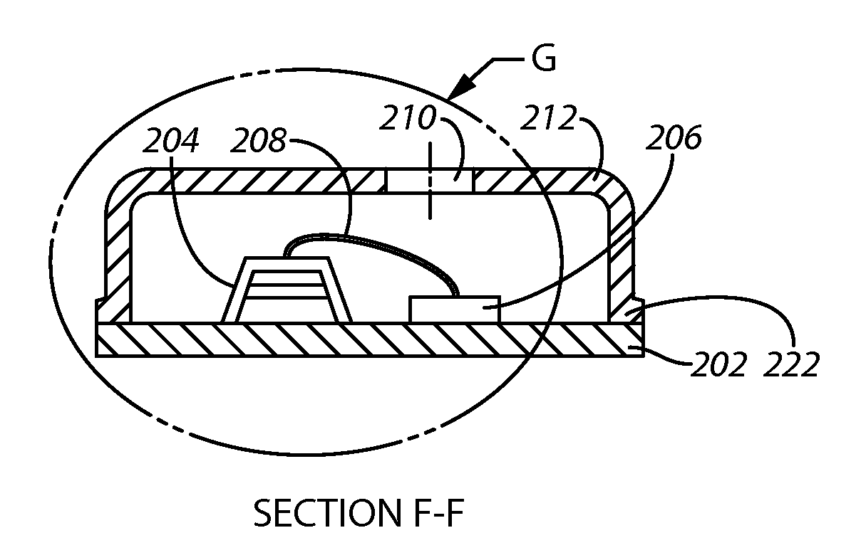
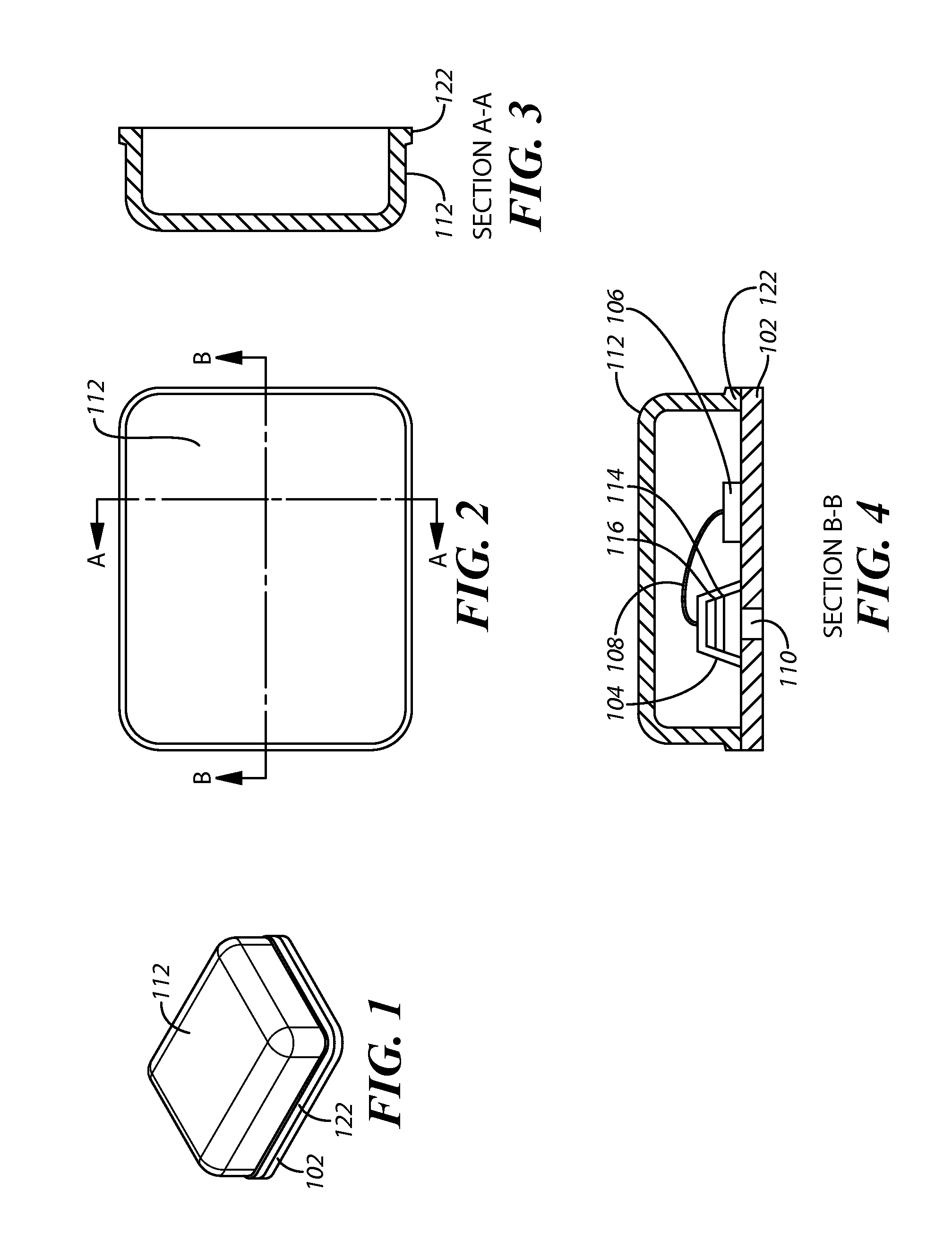
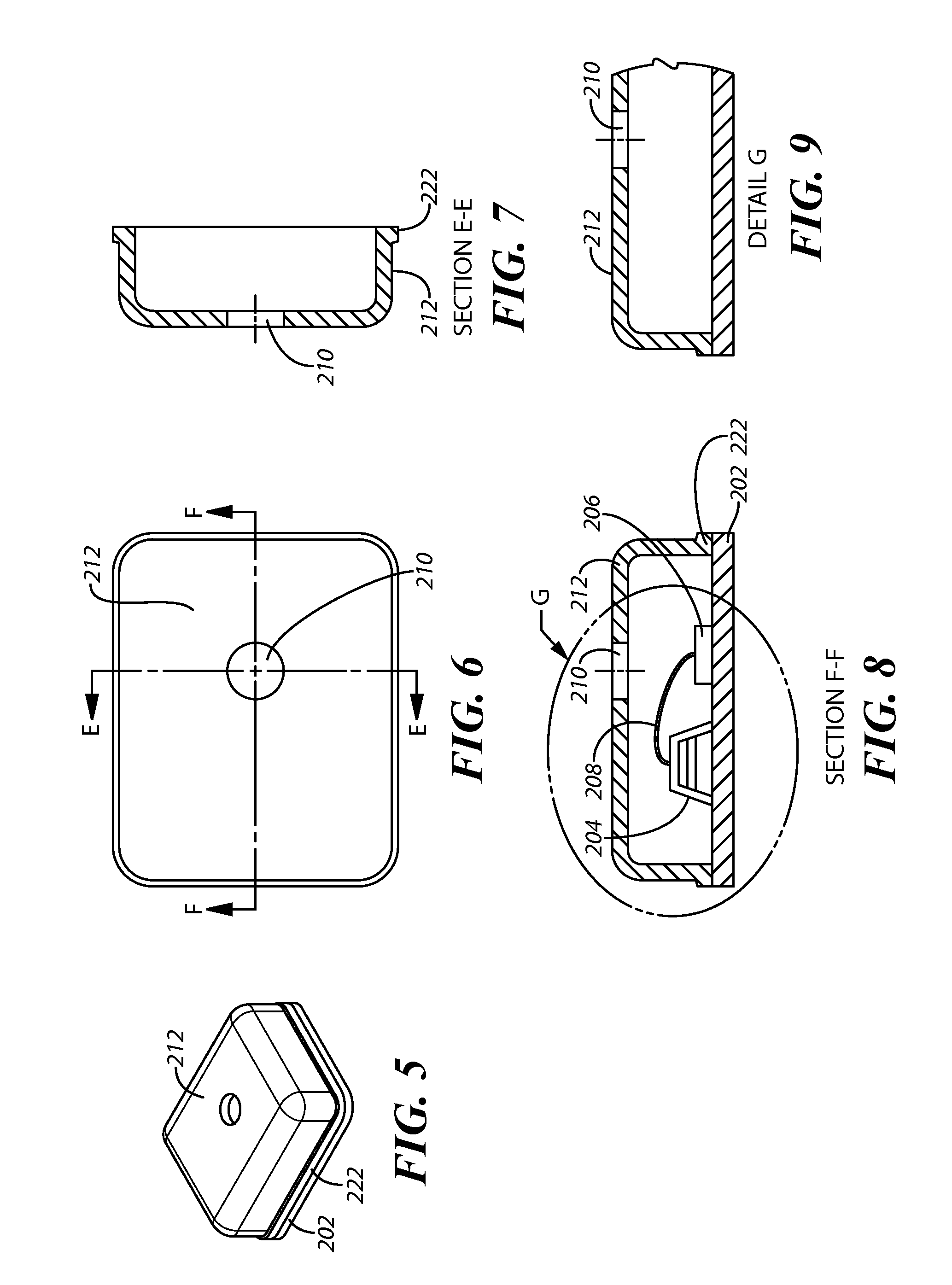
[0018]The present approaches provide a metal cover for a MicroElectroMechanical System (MEMS) microphone that eliminates or substantially reduces solder creep and provides other advantages described herein. In one aspect, a copper nickel zinc alloy that is approximately 55% copper, approximately 18% nickel, and approximately 27% zinc is used. In another aspect, this alloy has a material designation of C77000 under the Unified Numbering System (UNS). In one example, the alloy used may be the C77000 alloy produced by Wieland Metals, Inc.

[0019]In other aspects, the covers constructed of the copper nickel zinc alloys described herein are resistant to corrosion and have a good shelf life. Additionally, the covers constructed of the copper nickel zinc alloys provide for a good solderability and can be joined readily with soft solders. Further, the covers constructed of the copper nickel zinc alloys described herein do not need gold plating (or plating of any kind) or any surface finish. B...


PUM


Abstract

A microphone assembly includes a base, a cover, and a microelectromechanical system (MEMS) die. The cover extends at least partially over and is coupled to the base. The cover and the base form a cavity. The MEMS die is coupled to the base and disposed within the cavity. At least a portion of the cover is constructed of a copper-nickel-zinc alloy that is effective in preventing solder from moving from a first portion of the cover to a second portion of the cover.

Description

CROSS REFERENCE TO RELATED APPLICATIONS[0001]This patent claims benefit under 35 U.S.C. §119 (e) to U.S. Provisional Application No. 61 / 804,087 entitled “Cover for a MEMS Microphone” filed Mar. 21, 2013, and Application No. 61 / 804,004 entitled “Cover for a MEMS Microphone” filed Mar. 21, 2013, the contents of which are incorporated herein by reference in their entirety.TECHNICAL FIELD[0002]This application relates to MicroElectroMechanical components and, more specifically, the covers of these devices.BACKGROUND OF THE INVENTION[0003]MicroElectroMechanical System (MEMS) devices include microphones and speakers to mention two examples. In the case of a MEMS microphone, sound energy enters through a sound port and vibrates a diaphragm and this action creates a corresponding change in electrical potential (voltage) between the diaphragm and a back plate disposed near the diaphragm. This voltage represents the sound energy that has been received. Typically, the voltage is then transmitt...

Claims


Application Information

Patent Timeline
IPC IPC(8): H04R1/04B81B7/00
CPCB81B7/0077H04R1/04B81B7/0061B81B2201/0257B81B2207/012B81C1/00269B81C2203/0109B81C2203/035H04R2201/003
Inventor TALAG, DENNISFRIEL, KURTLIM, TONY
Owner KNOWLES ELECTRONICS INC
Why Eureka
Try Eureka