Magnetic resonance imaging method for the quantification of the t1 and/or t2 relaxation times in a sample

a magnetic resonance imaging and quantification method technology, applied in the field of magnetic resonance imaging, can solve the problems of ssfp-based imaging techniques, time-consuming 1 /sub>recovery or t2 /sub>decay curve, and hampered quantification of relaxation times. achieve the effect of fast and accurate quantification of longitudinal (t1)

Active Publication Date: 2014-10-02
UNIVSSPITAL BASEL
View PDF4 Cites 24 Cited by
  • Summary
  • Abstract
  • Description
  • Claims
  • Application Information

AI Technical Summary

Benefits of technology

[0008]It is an object of the present invention to provide a magnetic resonance imaging (MRI) method, which all...

Problems solved by technology

While morphology assessment by means of MRI has proven to be a diagnostic tool of great value in a wide area of diseases and applications, the early detection of subtle or diffuse pathological changes still represents a challenging, if not impossible task, even for a well-trained and experienced radiologist.
Likewise problematic are the examination of a certain treatment or of drug effects over a certain time period as well as clinical trials in drug research across different sites, due to the difficulties to guarantee an unbiased and objective assessment of MRI morphology images.
Acquiring the complete T1 recovery or T2 decay curve is time-consuming and frequently requires segmented imaging strategies.
As a result, accurate quantification...

Method used


Image

  • Magnetic resonance imaging method for the quantification of the t1 and/or t2 relaxation times in a sample
  • Magnetic resonance imaging method for the quantification of the t1 and/or t2 relaxation times in a sample
  • Magnetic resonance imaging method for the quantification of the t1 and/or t2 relaxation times in a sample

Examples


Embodiment Construction

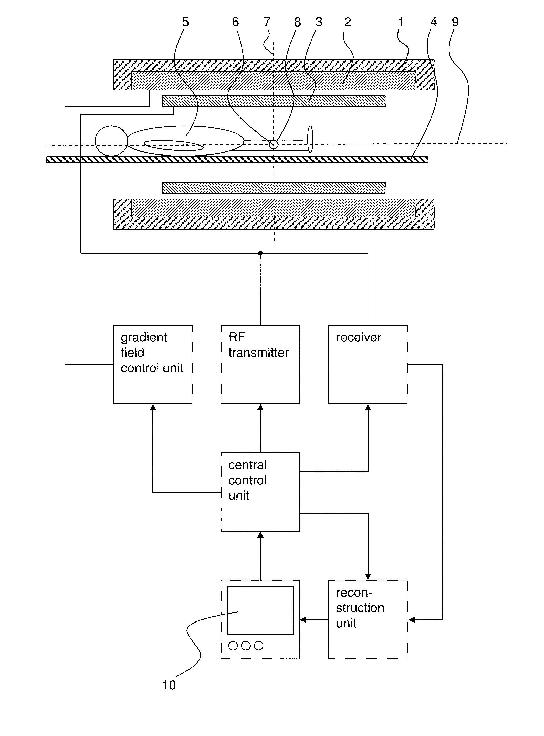
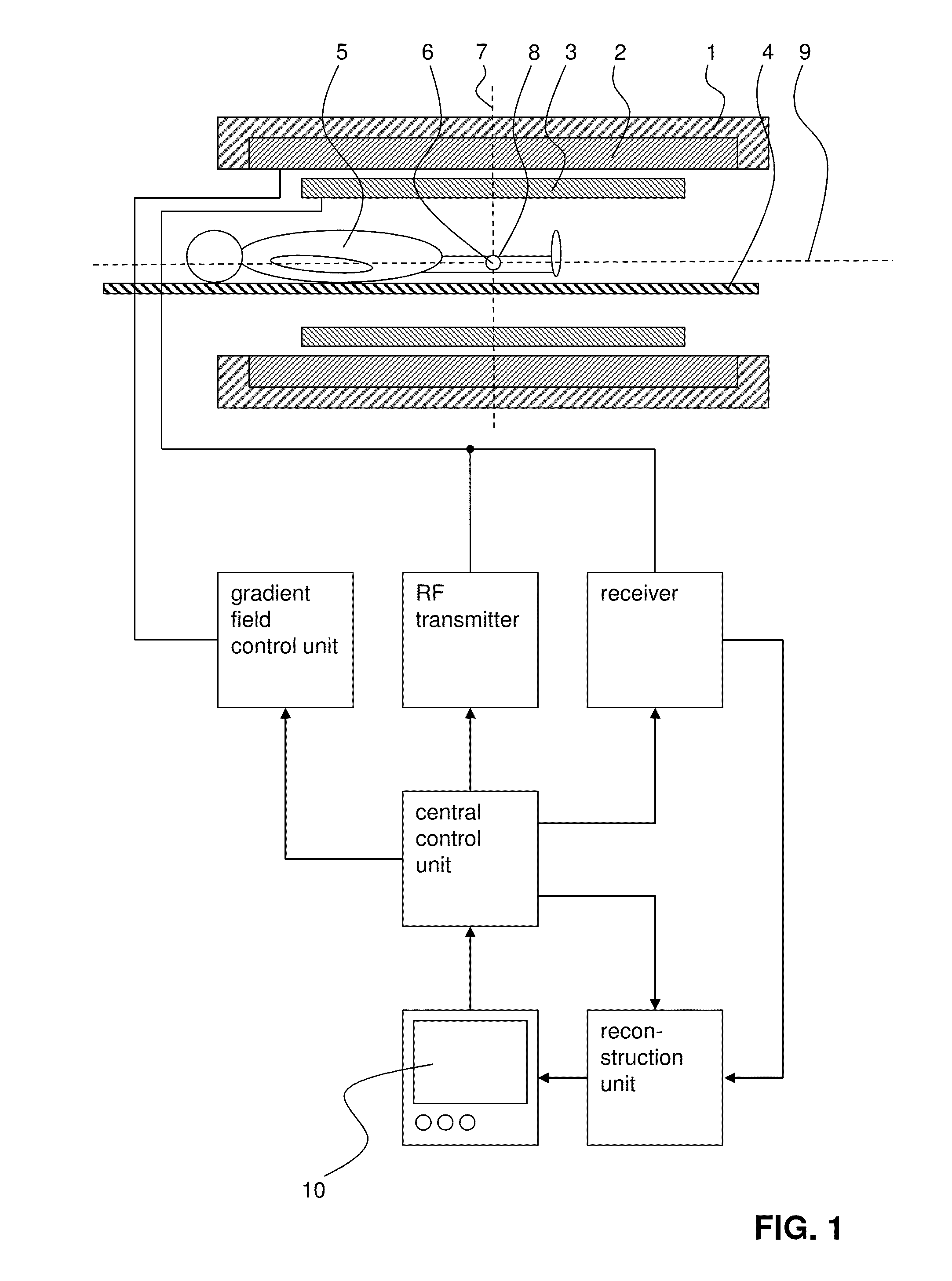
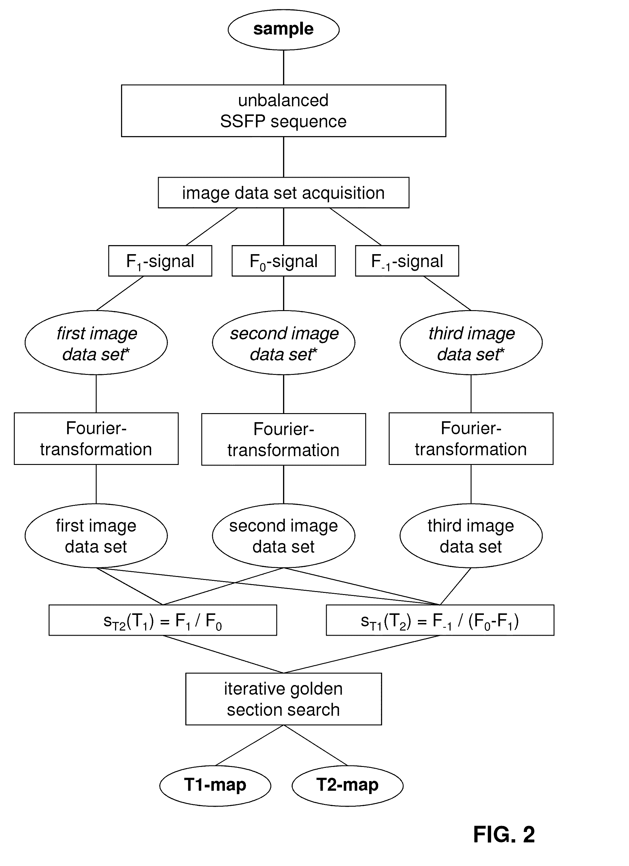
[0070]In FIG. 1, an exemplary MRI system is shown which serves to carry out the inventive method for the quantification of the longitudinal (T1) and transverse (T2) relaxation times in a sample. A flow chart illustrating an example of an inventive method is shown in FIG. 2.

[0071]The MRI system comprises a main magnet 1 for producing a main magnetic field B0. The main magnet 1 usually has the essential shape of a hollow cylinder with a horizontal bore. Inside the bore of the main magnet 1 a magnetic field is present, which is essentially uniform at least in the region of the isocenter 6 of the main magnet 1. The main magnet 1 serves to at least partly align the nuclear spins of a sample 5 arranged in the bore. Of course, the magnet 1 does not necessarily be cylinder-shaped, but could for example also be C-shaped.

[0072]The sample 5 is arranged in such a way on a moving table 4 in the bore of the main magnet 1, that the part of the sample 5, of which the longitudinal (T1) and / or transv...


PUM


Abstract

A magnetic resonance imaging (MRI) method for the quantification of the longitudinal (T1) and/or transverse (T2) relaxation times in a sample is provided. According to this MRI method a sample is subjected to an unbalanced steady state free precession (SSFP) sequence comprising a series of consecutive radiofrequency (RF) pulses. By means of this unbalanced SSFP sequence, the first order SSFP FID signal (F1), the lowest order SSFP FID signal (F0), and the lowest order SSFP Echo signal (F−1) are acquired. Based on the F0-signal, the F1-signal and the F−1-signal the longitudinal (T1) and/or transverse (T2) relaxation times of the sample are determined.

Description

TECHNICAL FIELD[0001]The present invention concerns a magnetic resonance imaging (MRI) method for the quantification of the longitudinal (T1) and / or transverse (T2) relaxation times in a sample. The present invention also concerns a computer program comprising executable instructions for carrying out such a MRI method as well as a MRI system configured for carrying out such a MRI method.PRIOR ART[0002]Magnetic resonance imaging (MRI) is a well-known medical imaging technique that allows visualizing internal structures of the human (and the animal) body in great detail. While morphology assessment by means of MRI has proven to be a diagnostic tool of great value in a wide area of diseases and applications, the early detection of subtle or diffuse pathological changes still represents a challenging, if not impossible task, even for a well-trained and experienced radiologist. Likewise problematic are the examination of a certain treatment or of drug effects over a certain time period a...

Claims


Application Information

Patent Timeline
IPC IPC(8): G01R33/44
CPCG01R33/5613G01R33/448
Inventor HEULE, RAHELBIERI, OLIVER
Owner UNIVSSPITAL BASEL
Why Eureka
Try Eureka