Establishing a Magnetic Resonance System Actuation Sequence

a magnetic resonance system and sequence technology, applied in the field of methods, can solve the problems of increasing the overall examination duration within the clinical routine, the computational complexity of the optimization method, and the data load of the optimization method caused by the field distribution map becoming problematic, so as to achieve the reduction of the overall duration of the field distribution map, save significant outlay, and reduce the computational complexity

Active Publication Date: 2014-10-02
SIEMENS HEALTHCARE GMBH
View PDF22 Cites 19 Cited by
  • Summary
  • Abstract
  • Description
  • Claims
  • Application Information

AI Technical Summary

Benefits of technology

[0018]The basic concept of both method embodiments is that the overall duration of the field distribution maps may be reduced by virtue of the fact that, initially, an optimization criterion, e.g., a similarity measure, is set. In accordance with the first embodiments, only field distribution maps are still acquired within a reduced scope. In accordance with the second embodiments, the number of field distribution maps is reduced to a smaller number of representation maps. What is allowed in both embodiments is that the reduced number of field distribution maps, acquired for the representation slices, or the representation maps ideally represent the in fact required number of field distribution maps (e.g., an individual field distribution map respectively for each slice) in respect of the given optimization criterion. As will be shown below, the amount of data required for the necessary field distribution maps therefore may be drastically reduced without a relevant reduction in quality of the imaging.
[0019]Depending on which variant of the method is employed, there may already be effects during the acquisition of the field distribution maps, by virtue of, as proposed by the first variant, it already being the case that fewer field distribution maps are acquired. However, the calculation of the radiofrequency pulse trains may at least be carried out with less computational complexity since of course the number of representation maps, which are included as input data in the optimization method for calculating the radiofrequency pulse trains, is reduced in comparison with the field distribution maps that are otherwise employed.
[0020]The two variants may also be employed in combination. For example, an acquisition scheme is already employed in the acquisition of the current field distribution maps such that field distribution maps are only established for a first number of representation slices. These acquired field distribution maps are subject to a further analysis in order to determine whether the field distribution maps are, in turn, represented in a suitable manner by an even smaller number of field distribution representation maps such that a predetermined optimization criterion is met, (e.g., that a specific cost or error limit value, which was defined in respect of the optimization criterion, is not exceeded). Using such a two-stage method, it is possible, in particular, to save significant outlay already during the acquisition of the field distribution maps. Nevertheless, there is no risk of, e.g., too few field distribution maps being acquired, which, under certain circumstances, turn out not to be completely ideal in respect of the predetermined optimization criterion. If, by contrast, more than the ideal number of field distribution maps were acquired in respect of the optimization criterion, a further reduction to the representation maps is possible in order to allow that work is only undertaken with the ideal number of representation maps in the calculation method for establishing the radiofrequency pulse train so as to minimize the computational outlay.

Problems solved by technology

On the other hand, the amount of data in the field distribution maps, which are included in the numerical optimization process, also has a significant influence on the computational complexity of the optimization method.
If the data relate to multi-slice applications, such as in e.g., fMRI (functional magnetic resonance imaging) methods, DWI (diffusion weighted imaging) methods and DTI (diffusion tensor imaging) methods, the data load within the optimization method caused by the field distribution maps becomes problematic, especially in view of the following aspects.
The acquisition of the field distribution maps, e.g., the B1 maps and the B0 maps, is relatively time-consuming for a multiplicity of slices and substantially increases the overall examination duration within the clinical routine.
This problem becomes more pronounced if a dynamic update, e.g., a reacquisition, of such field distribution maps is necessary due to patient movements.
The calculation time required to calculate a pTX-RF pulse sequence, specially adapted to the examination object or the examination situation, per slice, becomes unacceptable.
Currently, the calculation for a single slice is already a challenge.
This offers at least a compromise solution, but is in no way ideal.
Although, to this end, several slices may be linked to one another in order to combine the individual optimization for the individual slices to form a single, but large optimization problem, the optimization problem to be solved numerically rapidly grows to huge dimensions, and the dimensions exceed the calculation capacities of standard CPUs and standard RAM hardware.
Therefore, specific hardware-technical solutions may be required for this, which may make the devices significantly more expensive.

Method used


Image

  • Establishing a Magnetic Resonance System Actuation Sequence
  • Establishing a Magnetic Resonance System Actuation Sequence
  • Establishing a Magnetic Resonance System Actuation Sequence

Examples


Embodiment Construction

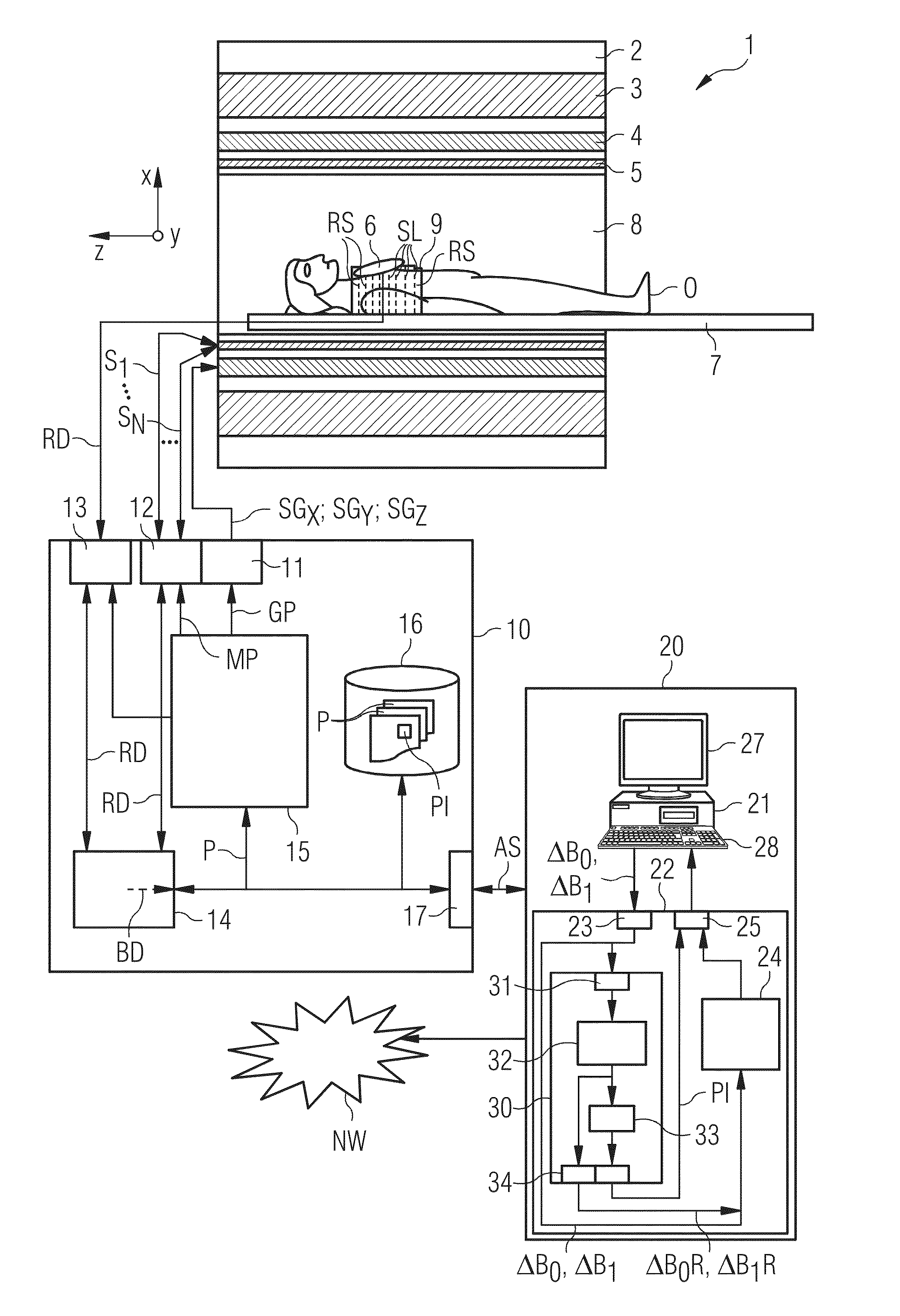
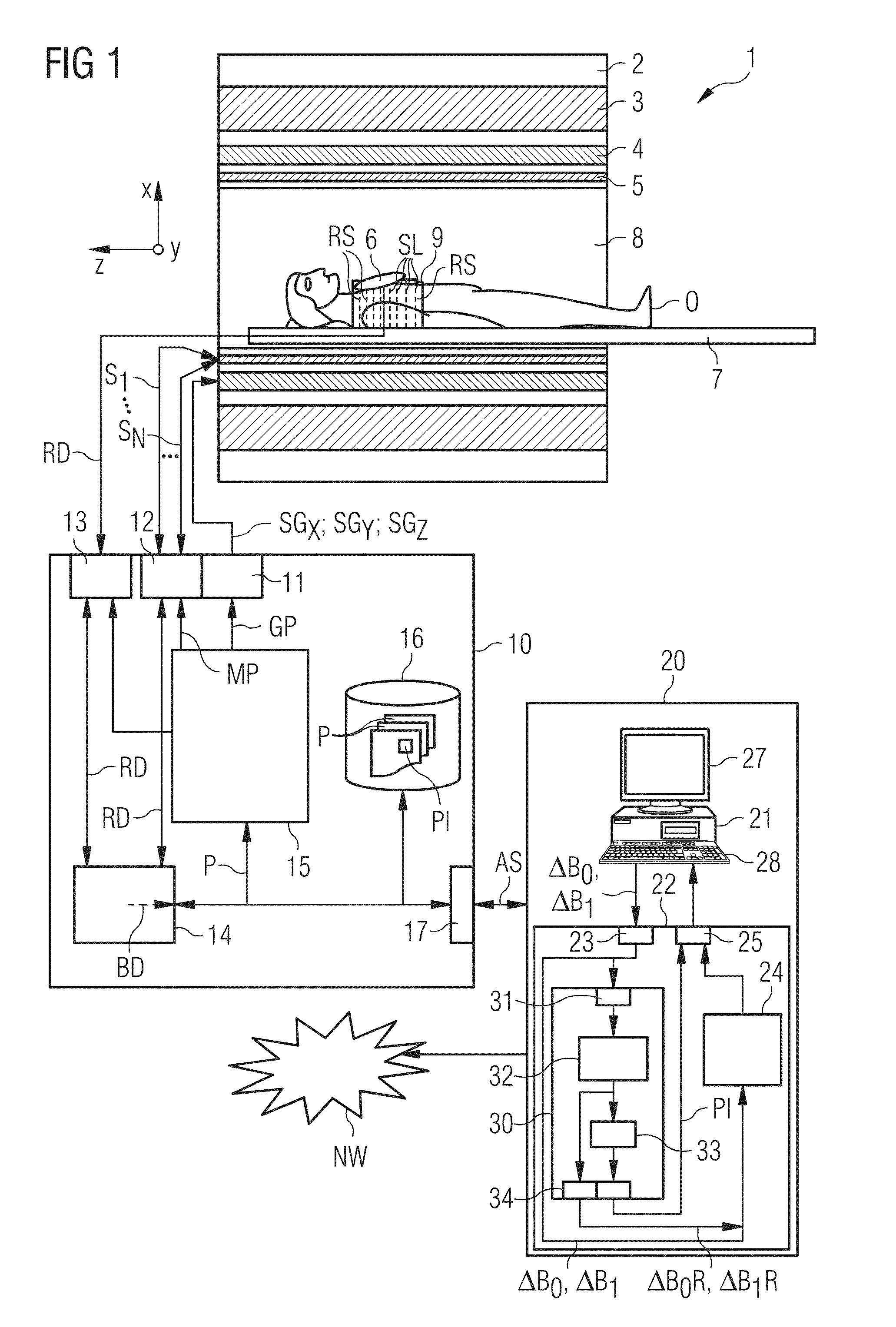
[0069]FIG. 1 depicts, in a schematic manner, a magnetic resonance machine 1. The magnetic resonance machine 1 includes the actual magnetic resonance scanner 2 with an examination space 8 or patient tunnel situated therein. A couch 7 may be displaced into this patient tunnel 8 such that, during an examination, an examination object O (patient / subject) may be placed at a specific position within the magnetic resonance scanner 2 relative to the magnet system and radiofrequency system arranged therein and also be moved between different positions during a measurement.

[0070]Essential components of the magnetic resonance scanner 2 are a main field magnet 3, a gradient system 4 with magnetic field gradient coils for applying any magnetic field gradients in x-, y- and z-directions, and also a whole body radiofrequency coil 5. Magnetic resonance signals induced in the examination object O may be received by the whole body coil 5 with which the radiofrequency signals may also be emitted for i...


PUM


Abstract

A method for establishing a magnetic resonance system actuation sequence is described. A first number of field distribution maps are acquired for slices of the measurement region, and a radiofrequency pulse train is established on the basis thereof for the magnetic resonance system actuation sequence. This acquisition of the first number of field distribution maps may be brought about on the basis of an acquisition scheme. A reduced number of field distribution representation maps are established on the basis of the acquired field distribution maps, which field distribution representation maps represent the first number of acquired field distribution maps in accordance with a predetermined optimization criterion, and the radiofrequency pulse train is established on the basis of the field distribution representation maps.

Description

CROSS-REFERENCE TO RELATED APPLICATIONS[0001]This application claims the benefit of DE 10 2013 205 785.7, filed on Apr. 2, 2013, which is hereby incorporated by reference in its entirety.TECHNICAL FIELD[0002]The embodiments relate to methods for establishing a magnetic resonance system actuation sequence. Furthermore, the embodiments relate to methods for operating a magnetic resonance system, a field distribution map analysis apparatus for use in a method for establishing a magnetic resonance system actuation sequence, a control sequence establishment apparatus, and a magnetic resonance system with such a control sequence establishment apparatus.BACKGROUND[0003]In a magnetic resonance imaging system (abbreviated “magnetic resonance system”) the body to be examined may be exposed to a relatively high main magnetic field (the so-called “B0 field”), for example of 1.5, 3, or 7 Tesla, with the aid of a main field magnet system. Additionally, a magnetic field gradient is applied with th...

Claims


Application Information

Patent Timeline
Patent Type & Authority Applications(United States)
IPC IPC(8): G01R33/54
CPCG01R33/583G01R33/243G01R33/543G01R33/246
Inventor BECK, THOMASSCHNEIDER, RAINER
Owner SIEMENS HEALTHCARE GMBH
Why Eureka
Try Eureka