Idling stop control device, vehicle and vehicle control method
a technology of idling stop and control device, which is applied in the direction of engine starters, machines/engines, instruments, etc., can solve the problems of frequent stop and restart of engines, and achieve the effect of improving the fuel consumption of the vehicl
- Summary
- Abstract
- Description
- Claims
- Application Information
AI Technical Summary
Benefits of technology
Problems solved by technology
Method used
Image
Examples
first embodiment
A. First Embodiment
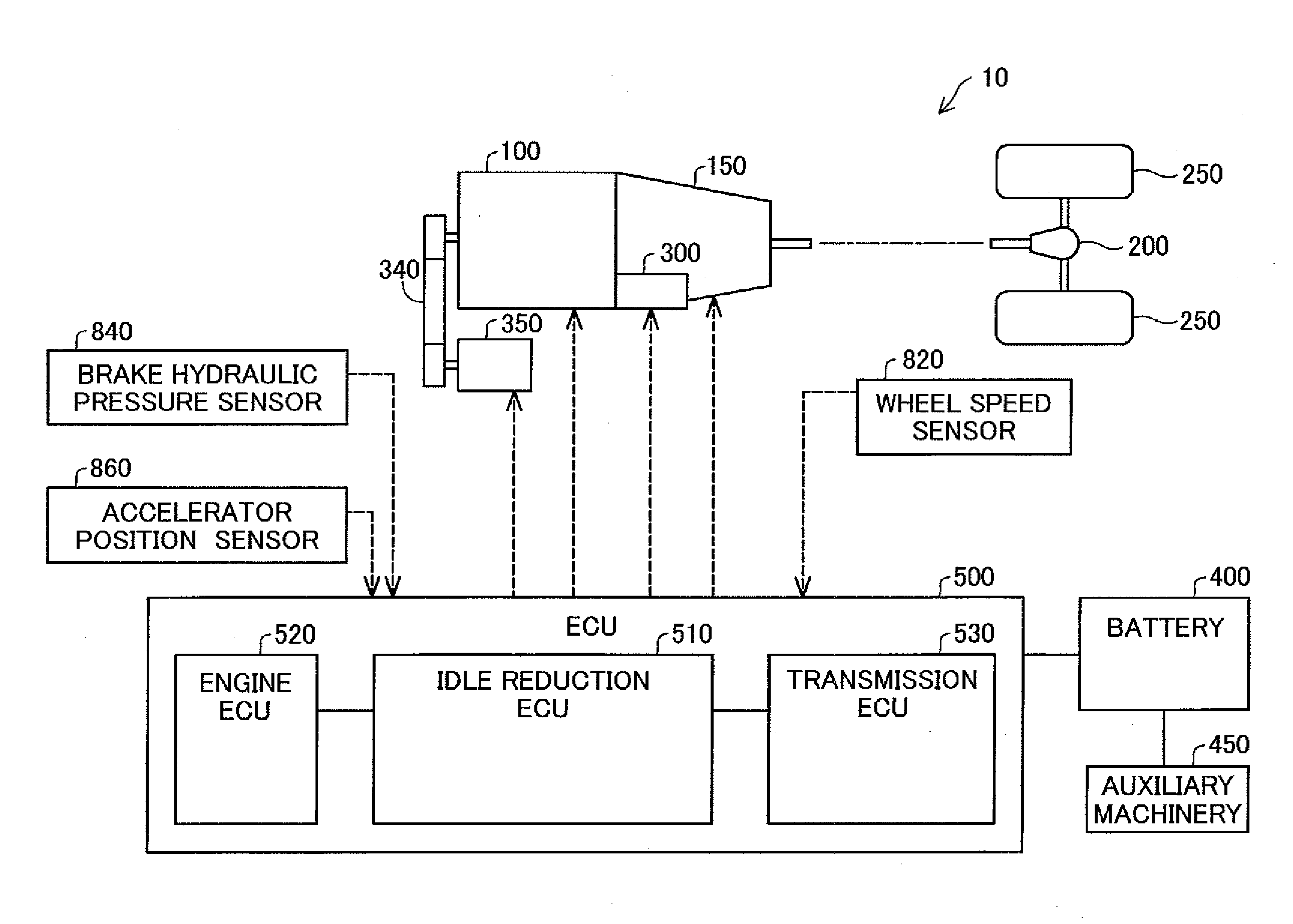
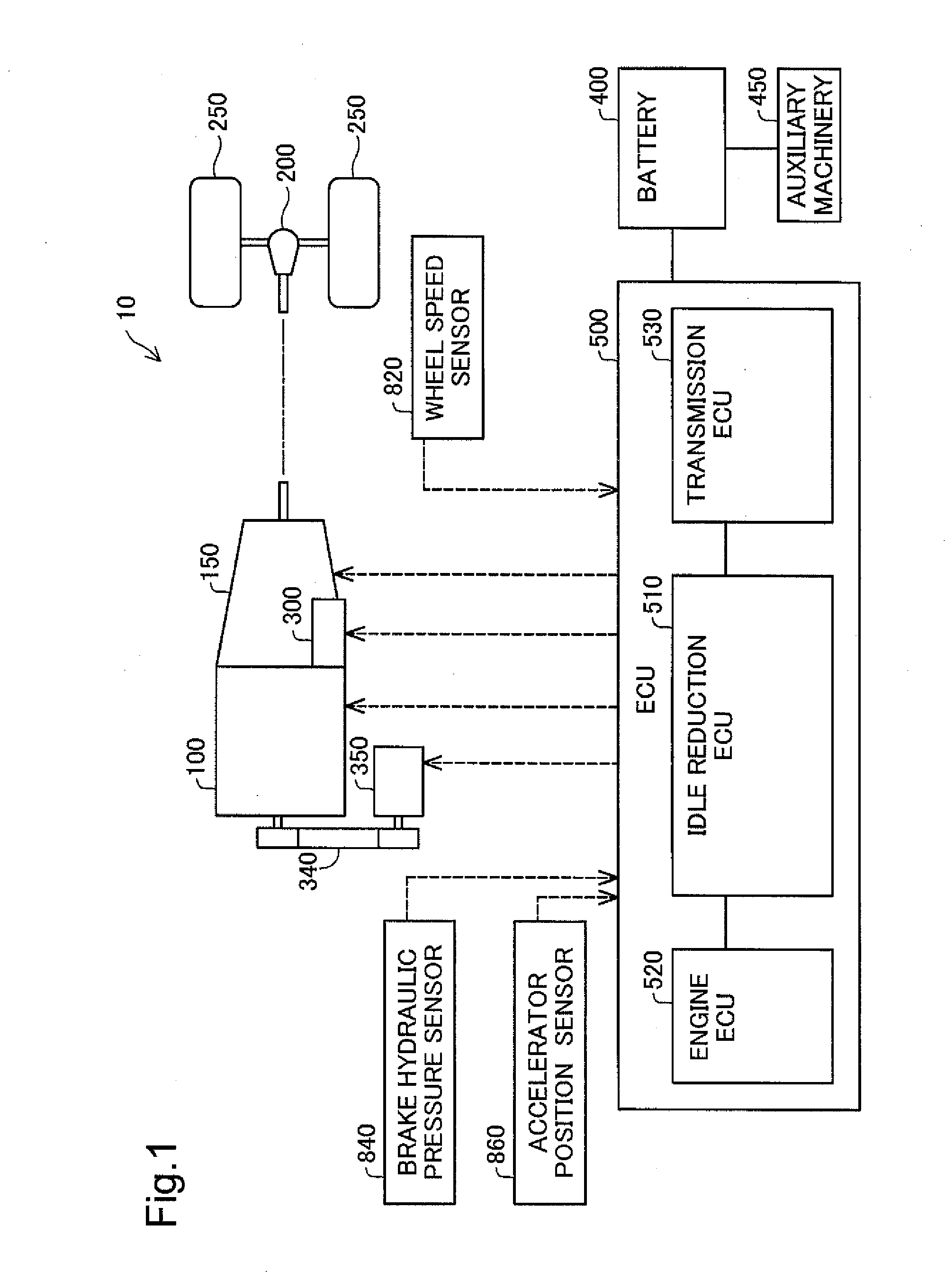
[0056]FIG. 1 is a diagram illustrating the general configuration of an automobile according to a first embodiment. The automobile 10 is a vehicle having idle reduction function. The automobile 10 includes an engine 100, an automatic transmission 150, a differential gear 200, drive wheels 250, a starter 300, an alternator 350, a battery 400 and an electronic control unit (ECU) 500.
[0057]The engine 100 is an internal combustion engine that generates power by combustion of a fuel such as gasoline or light oil. The power of the engine 100 is transmitted to the automatic transmission 150, while being transmitted to the alternator 350 via a drive mechanism 340. The output of the engine 100 is changed according to the amount of the driver's accelerator pedal operation by the electronic control unit 500.
[0058]The automatic transmission 150 automatically changes the gear ratio (so-called gear shifting). The power (rotation speed·torque) of the engine 100 is subjected to ge...
second embodiment
B. Second Embodiment
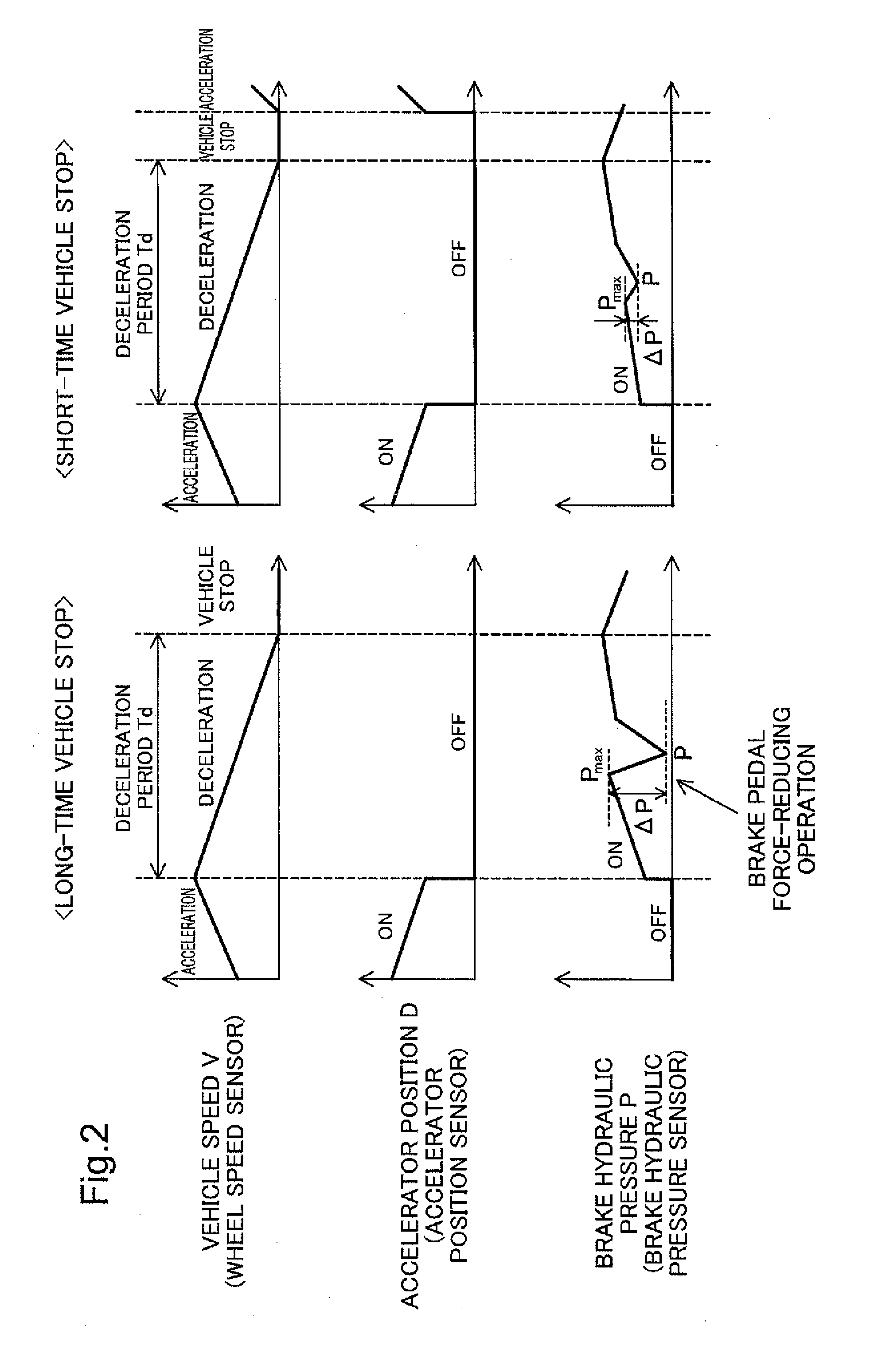
[0087]A second embodiment describes a configuration of predicting whether a vehicle stop is a long-time vehicle stop or a short time vehicle stop, based on the intensity of brake pedal operation during the deceleration period Td in the idle reduction control. The general configuration of the automobile 10 is identical with that of the first embodiment and is thus not specifically described here.
[0088]FIG. 5 is a diagram illustrating the details of idle reduction control according to the second embodiment. The idle reduction ECU 510 predicts whether a vehicle stop is a long-time vehicle stop or a short-time vehicle stop, based on the magnitude of the maximum brake hydraulic pressure Pmax during the deceleration period Td. As described above, the long-time vehicle stop includes various vehicle stops that need adjustment of the vehicle stop position to a specified position, for example, a vehicle stop at a traffic light or a vehicle stop for parking During the decel...
third embodiment
C. Third Embodiment
[0093]A third embodiment describes a configuration of predicting whether a vehicle stop is a long-time vehicle stop or a short time vehicle stop, based on the intensity of brake pedal operation immediately before a stop of the automobile 10 in the idle reduction control. The general configuration of the automobile 10 is identical with that of the first embodiment and is thus not specifically described here.
[0094]FIG. 8 is a diagram illustrating the details of idle reduction control according to the third embodiment. The idle reduction ECU 510 predicts whether a vehicle stop is a long-time vehicle stop or a short-time vehicle stop, based on the magnitude of the maximum brake hydraulic pressure Pmax immediately before a stop of the automobile 10. As described above, the long-time vehicle stop includes various vehicle stops that need adjustment of the vehicle stop position to a specified position. During the deceleration period Td prior to a long-time vehicle stop, t...
PUM
 Abstract
Description
Claims
Application Information
 - R&D
- Intellectual Property
- Life Sciences
- Materials
- Tech Scout
- Unparalleled Data Quality
- Higher Quality Content
- 60% Fewer Hallucinations
Browse by: Latest US Patents, China's latest patents, Technical Efficacy Thesaurus, Application Domain, Technology Topic, Popular Technical Reports.
© 2025 PatSnap. All rights reserved.Legal|Privacy policy|Modern Slavery Act Transparency Statement|Sitemap|About US| Contact US: help@patsnap.com


