Exhaust gas inlet structure of an exhaust gas recirculation cooler

a technology of exhaust gas recirculation and inlet structure, which is applied in the direction of heat exchange apparatus safety devices, machines/engines, light and heating apparatus, etc., can solve the problems of ineffective egr coolers, vibration during operation renders bellows or insulated pipes ineffective, and reduces wall temperature , improves axial thermal expansion displacement compensation, and improves vibration resistance performance

Active Publication Date: 2014-10-09
ZHEJIANG YINLUN MACHINERY
View PDF4 Cites 15 Cited by
  • Summary
  • Abstract
  • Description
  • Claims
  • Application Information

AI Technical Summary

Benefits of technology

[0017]The above-mentioned exhaust gas inlet structure of the EGR cooler provided by the present invention features the newly-added pre-cooling water chamber to decrease the wall temperature of the main board and inlet chamber, the newly-added supporting in the middle part of the insulated pipe to improve the vibration-proof performance and the special structure of the inlet chamber to increase the axial thermal expansion displacement compensation inside the EGR cooler. The improvements have significantly improved the reliability of the EGR cooler.

Problems solved by technology

Therefore, during its working process, the wall temperature of the cooler pipes will be relatively high and the longitudinal thermal expansion will result in the deformation at the joint of cooling pipe and the main board, rendering the joint ineffective.
Severe deformation usually renders the EGR cooler ineffective.
Moreover, considering the design that the inner insulated pipe of the bellow of the gas inlet pipe is fixed to the inlet pipe only at one end, if the insulated pipe is relatively long, the vibration during operation will render the bellow or the insulated pipe ineffective.

Method used


Image

  • Exhaust gas inlet structure of an exhaust gas recirculation cooler
  • Exhaust gas inlet structure of an exhaust gas recirculation cooler
  • Exhaust gas inlet structure of an exhaust gas recirculation cooler

Examples


Embodiment Construction

[0059]A further description of the present invention with specific embodiment will be given below with reference to the drawings.

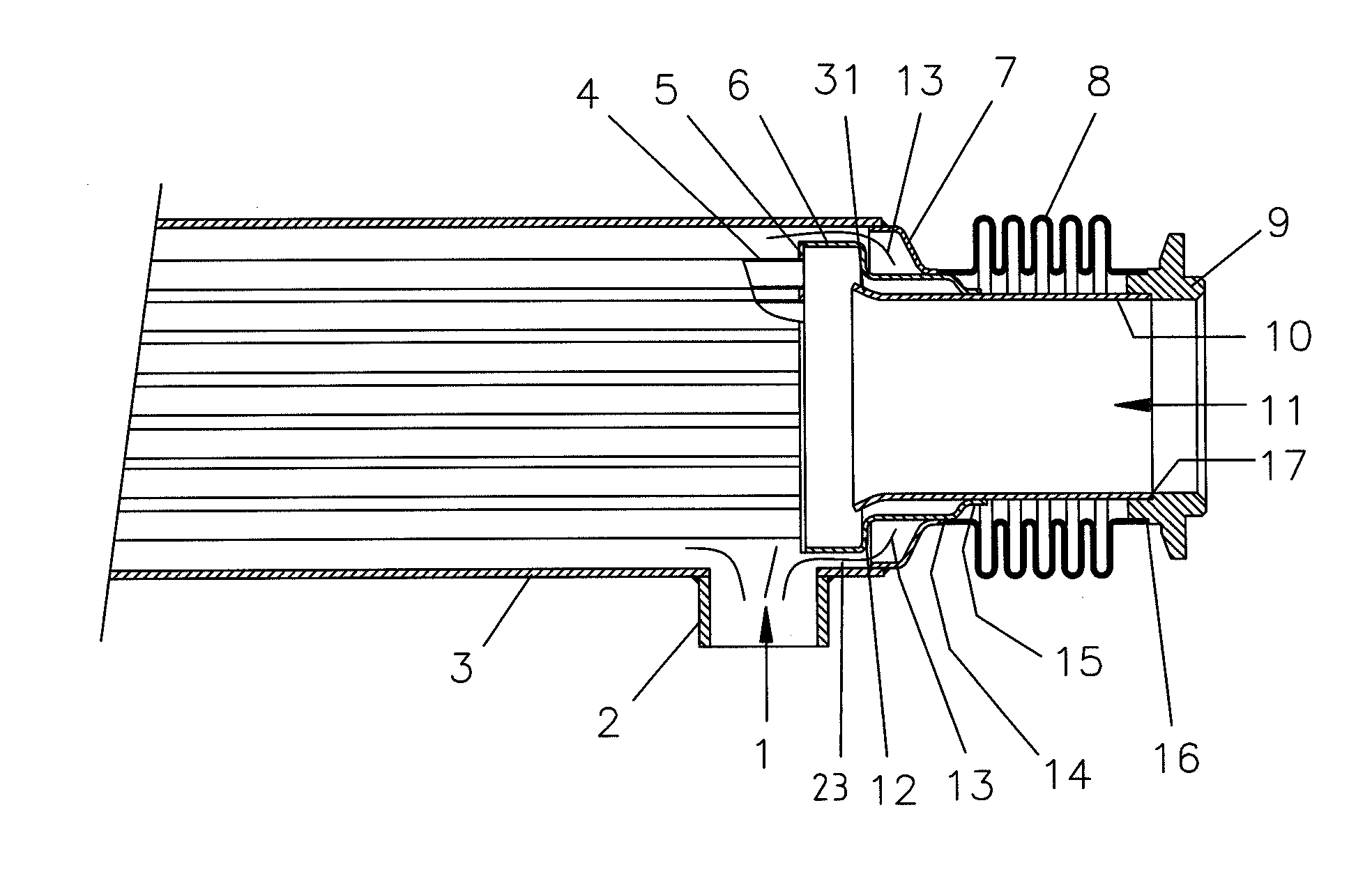
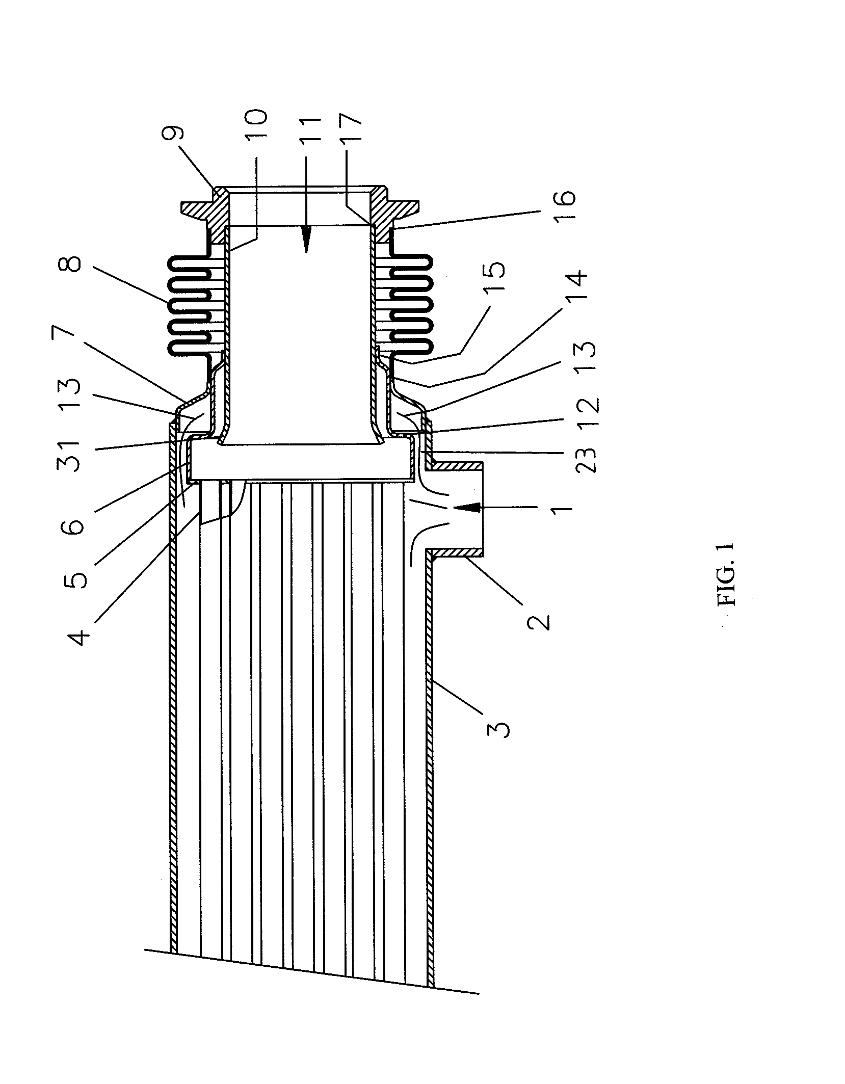
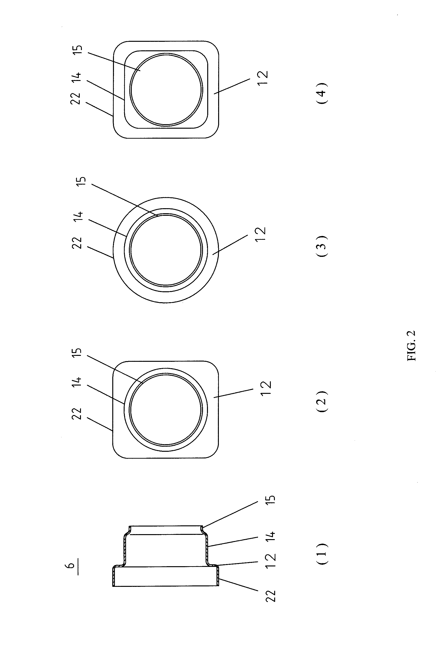
[0060]With reference to FIG. 1 and FIG. 2, the exhaust gas inlet structure of the EGR cooler of the present invention includes a water shell 3, a gas inlet pipe 9, a bellow 8, an insulated pipe 10, an inlet chamber 6, a pre-cooling water chamber 7 and a main board 5. The water shell 3 is equipped with a water inlet pipe 2 and a core 4 within, one end of which is connected to the main board 5. The gas inlet pipe 9, bellow 8, pre-cooling water chamber 7 and water shell 3 are connected with a brazing or an argon arc welding in sequence. The insulated pipe 10 is placed within the bellow 8 and welded with the gas inlet pipe 9 at one end while the other end is suspended. The gas inlet chamber 6 is a two-grade reducing pipe including a large-bore end 22, a middle pipe body 14 and a small-bore end 15. The large-bore end 22 is welded with the main board 5 to form a...


PUM


Abstract

The present invention discloses an exhaust gas inlet structure of an exhaust gas recirculation (EGR) Cooler which includes a water shell, a gas inlet pipe, a bellow, an insulated pipe, an inlet chamber, a pre-cooling water chamber and a main board. The water shell is equipped with a water inlet pipe. Its main feature is the insulated pipe is placed within the bellow and connected with the gas inlet pipe at one end while the other end is suspended. The large-bore end of the inlet chamber is connected with the main board to form a gas inlet cavity while leaving a space to form a coolant channel between the joining part and the water shell. An external surface of a middle pipe body connects to the bellow to form a pre-cooling cavity connected to the coolant channel. The advantages of the present invention are as follow: newly-added pre-cooling water chamber reduces the wall temperature of the main board and the inlet chamber; newly-added supporting in the middle part of the insulated pipe improves the vibration-proof function of the insulated pipe; the special structure of the inlet chamber increases the ability of the axial displacement compensation. The above-mentioned improvement of the present invention significantly improves the reliability of the EGR cooler.

Description

FIELD OF THE INVENTION[0001]The present invention belongs to the field of heat exchanger technology, involving structure form and structure reliability improvements of an engine exhaust gas recirculation cooler, more specifically, relates to an exhaust gas inlet structure of an exhaust gas recirculation (EGR) cooler.BACKGROUND OF THE INVENTION[0002]Exhaust gas recirculation technology is one of the main technologies for engines to achieve emission above national standard No. 4. Before recirculation entering an engine cylinder, exhaust gas shall pass through the EGR cooler to cool to a specific temperature. The working temperature of the EGR cooler at its heat side of high-temperature exhaust gas is usually 120° C.-30° C. and 80° C.-120° C. at its cool side of coolant. Therefore, during its working process, the wall temperature of the cooler pipes will be relatively high and the longitudinal thermal expansion will result in the deformation at the joint of cooling pipe and the main bo...

Claims


Application Information

Patent Timeline
Patent Type & Authority Applications(United States)
IPC IPC(8): F02M25/07
CPCF02M25/0726F28D7/16F28D21/0003F28F9/02F28F9/0239F28F2009/0295F28F2265/26F02M26/13F02M26/32F28D7/00Y02T10/12
Inventor ZHANG, WENFENGQIN, XIAOJUNYOUQI, ZHAOLIU, HAO
Owner ZHEJIANG YINLUN MACHINERY
Why Eureka
Try Eureka