Segment coil, method of manufacturing segment coil, wire rod for segment coil, and stator

a technology of segment coils and wire rods, applied in the direction of dynamo-electric components, solid insulation, windings, etc., can solve the problems of poor operability, inability to flow high current, and winding around the slot opening on the inner side without damage, so as to prevent eddy current or magnetic flux leakage

Inactive Publication Date: 2014-10-09
TOYOTA JIDOSHA KK
View PDF8 Cites 27 Cited by
  • Summary
  • Abstract
  • Description
  • Claims
  • Application Information

AI Technical Summary

Benefits of technology

[0087]A stator capable of achieving effective prevention of eddy current or magnetic flux leakage can be obtained.

Problems solved by technology

It has been difficult, however, to wind the winding around the slot opening on the inner side without causing damage and operability has been poor.
In addition, since a large diameter of a bendable winding cannot be set, a high current cannot flow.
Therefore, it is difficult to achieve higher output of a motor.
Therefore, a cross-sectional area of a conductor is accordingly decreased and it is also difficult to improve a space factor.

Method used


Image

  • Segment coil, method of manufacturing segment coil, wire rod for segment coil, and stator
  • Segment coil, method of manufacturing segment coil, wire rod for segment coil, and stator
  • Segment coil, method of manufacturing segment coil, wire rod for segment coil, and stator

Examples


third embodiment

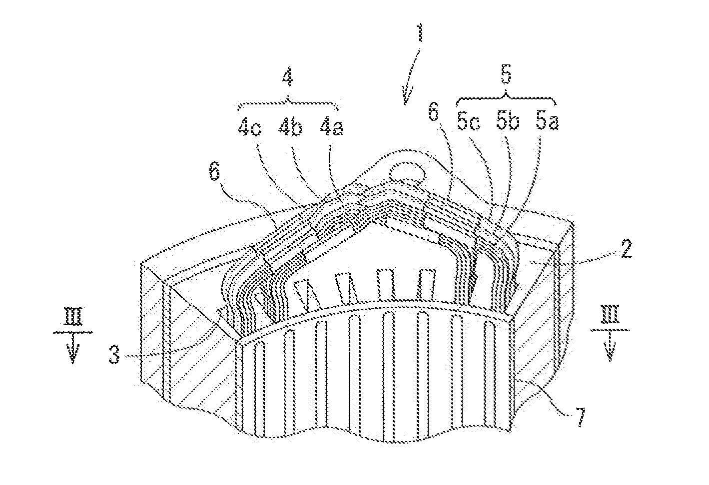
[0173]FIGS. 11 to 15 show the invention of the present application. In the present embodiment as well, a segment coil attached on an innermost circumferential side in the direction of radius of the slot and opposed to the rotor is formed from a plurality of divided wires as divided in the circumferential direction of the annular core.

[0174]As shown in FIG. 11, first colored identification portions 451b, 452a, 452b, 453a, 453b, 454a, 454b, and 455a allowing identification of connection portions 505a and 505b of a series of connected segment coils A10 to A50 are provided. Basically, in segment coils A20 to A40 located in an intermediate portion, straight portions C shown in FIG. 13 are attached to the same slot. At least one of segment coil A10 arranged on the innermost side in the direction of radius of the stator and segment coil A50 arranged on the outermost side in the direction of radius of the stator is connected to a coil end portion extending from a straight portion attached t...

first embodiment

[0185]A construction and a form of second colored identification portions 465A1, 465B1, 465C1, and 465D1 are not particularly limited. For example, as shown in FIG. 15, as in the first embodiment, second colored identification portion 465A1 can be formed by applying a paint having a corresponding color to a prescribed region on an insulating coating 408 provided in a conductor 407.

[0186]The second colored identification portion can be obtained by bonding a color tape material or attaching a color tube material to a prescribed region in a segment coil. For example, an insulating resin tape material (trade name Kapton tape) manufactured by Permacel can be adopted as the color tape material. A heat-shrinkable tube material such as an insulating resin tube (trade name Sumitube) manufactured by Sumitomo Electric Industries, Ltd. can be adopted as the color tube material. By adopting an insulating paint or tape material or tube material, the second colored identification portion can funct...

fourth embodiment

[0191]FIGS. 16A and 16B to 19 show the invention of the present application. Since the embodiment is similar to the embodiments described above other than a joint portion of a coil end portion, description will not be provided.

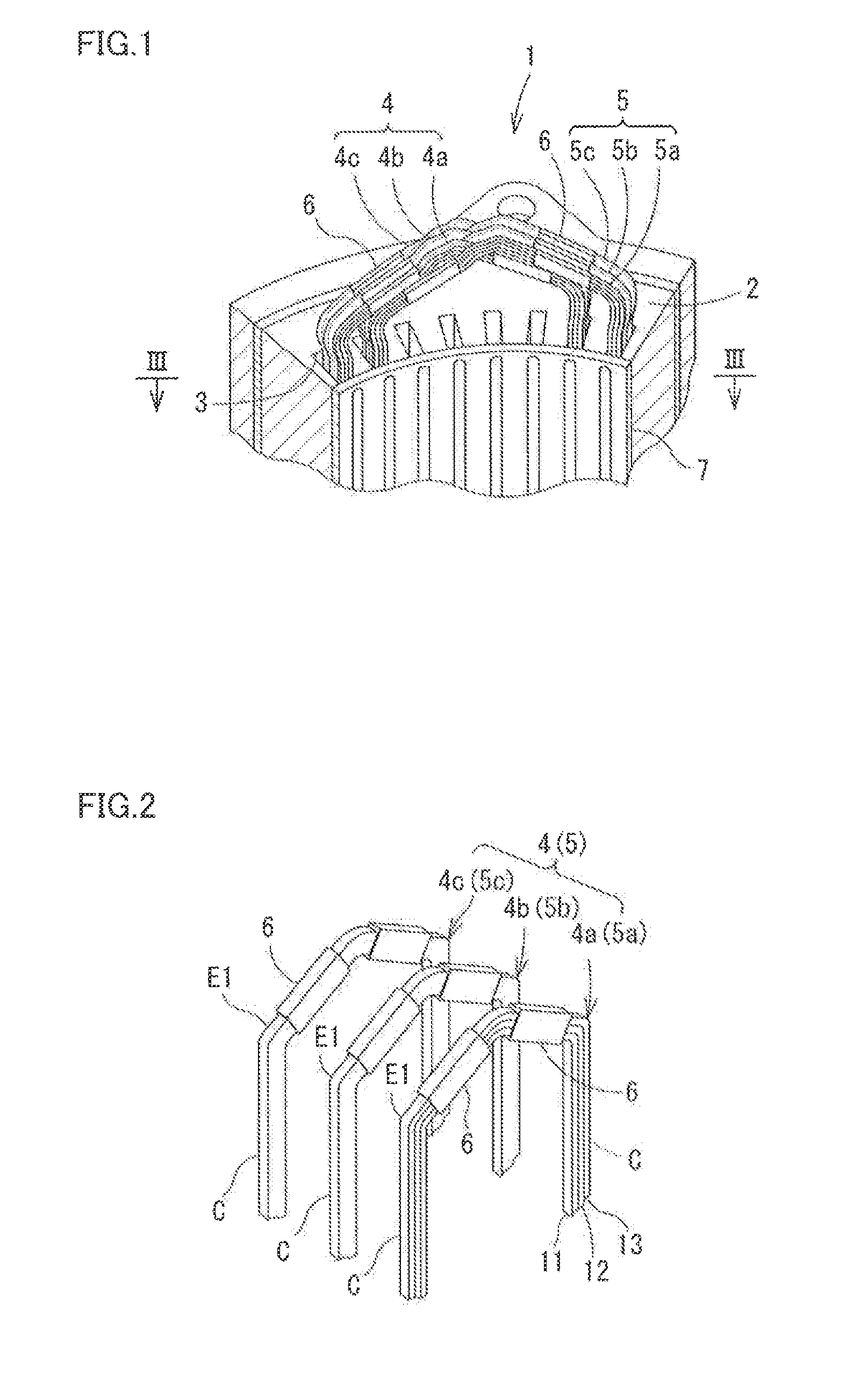
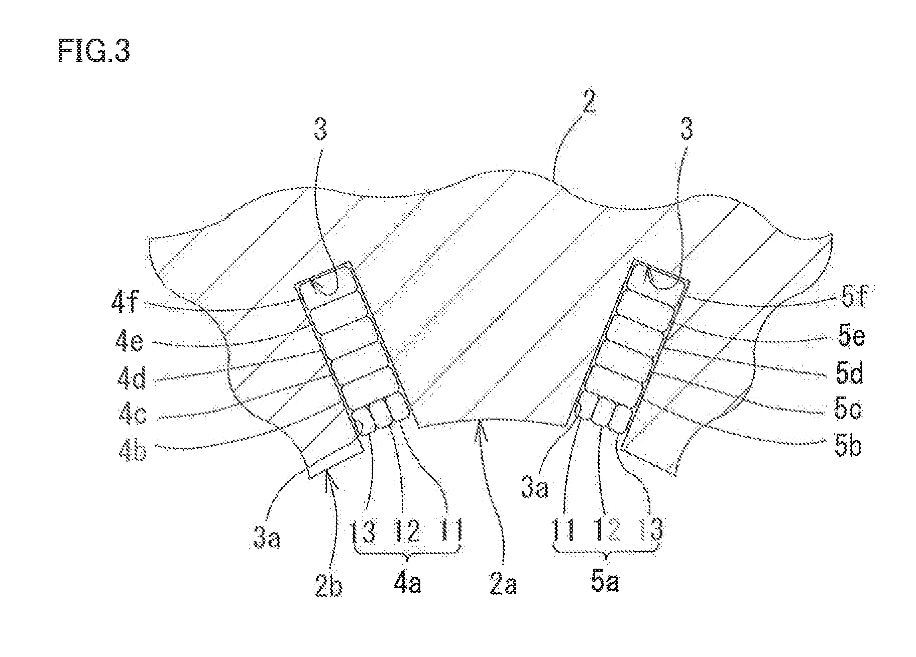
[0192]As shown in FIG. 16B, a segment coil 612 mainly includes a pair of linear straight portions C accommodated in a slot 611c and a pair of coil end portions E1 and E2 protruding outward of slot 611c. A joint portion S having a joint surface S1 for joining adjacent segment coils 612 in the same phase is provided at a tip end of one E2 (on a lower side in the figure in the present embodiment) of a pair of coil end portions E1 and E2. More specifically, as shown in FIGS. 16B and 17, an end portion of coil end portion E2 is twisted (bent) outward in a direction of radius of annular core 611. Thus, such a pair of joint portions S that joint surface S thereof is in parallel to the direction of radius of annular core 611 is provided at the tip end of coil end port...


PUM

PropertyMeasurementUnit
thicknessaaaaaaaaaa
thicknessaaaaaaaaaa
thicknessaaaaaaaaaa

Abstract

A segment coil capable of achieving effective prevention of magnetic flux leakage or eddy current and enhancing efficiency of a motor is provided. Segment coils in stator of a rotating electric machine including an annular core and rectangular wire coils in a plurality of layers, which are attached on an innermost circumferential side in a direction of radius of a slot formed in an inner circumferential portion of the annular core and are opposed to a rotor, are each constituted of a plurality of divided wires as divided in a circumferential direction of the annular core. The plurality of divided wires are integrally joined in coil end portions extending from the slot.

Description

TECHNICAL FIELD[0001]The present application claims priority to Japanese Patent Applications Nos. 2011-235979, 2011-262325, 2012-005797, 2012-016236, 2012-023874, 2012-045004, and 2012-198626 filed on Oct. 27 and Nov. 30, 2011, Jan. 16 and 30, Feb. 7, Mar. 1, and Sep. 10, 2012, respectively, the disclosure of which is incorporated by reference herein in its entirety.[0002]The invention of the present application relates to a segment coil included in a stator of a rotating electric machine, a method of manufacturing a segment coil, a wire rod for a segment coil, and a stator. Specifically, the invention relates to a segment coil capable of achieving less eddy current or magnetic flux leakage caused in a coil accommodated in a stator and a higher space factor.BACKGROUND ART[0003]For example, a stator of a motor implemented as a rotating electric machine includes coils in an annular core. In the annular core, a plurality of slots opening on an inner side are provided at prescribed inte...

Claims


Application Information

Patent Timeline
Patent Type & Authority Applications(United States)
IPC IPC(8): H02K3/28H02K15/04
CPCH02K3/04H02K3/34H02K15/0414H02K15/10H02K3/28H02K15/04H02K3/12H02K15/045H02K15/105H02K3/38H02K15/0081Y10T29/49009
Inventor TAKIZAWA, KEIJISUZUKI, TOMOKAIIZUKA, SHINICHISAKA, HIRONOBUARIYOSHI, TAKESHI
Owner TOYOTA JIDOSHA KK
Why Eureka
Try Eureka