

Optical distance measuring apparatus
a technology of optical distance measurement and measuring apparatus, which is applied in the direction of distance measurement, instruments, surveying and navigation, etc., can solve the problems of light receiving intensity difference, difficult to realize high distance measurement accuracy with respect to the measuring object, etc., and achieve high distance measurement accuracy and reduce detection errors of optical distance measuring apparatus
- Summary
- Abstract
- Description
- Claims
- Application Information
AI Technical Summary
Benefits of technology
Problems solved by technology
Method used
Image

Examples
first embodiment
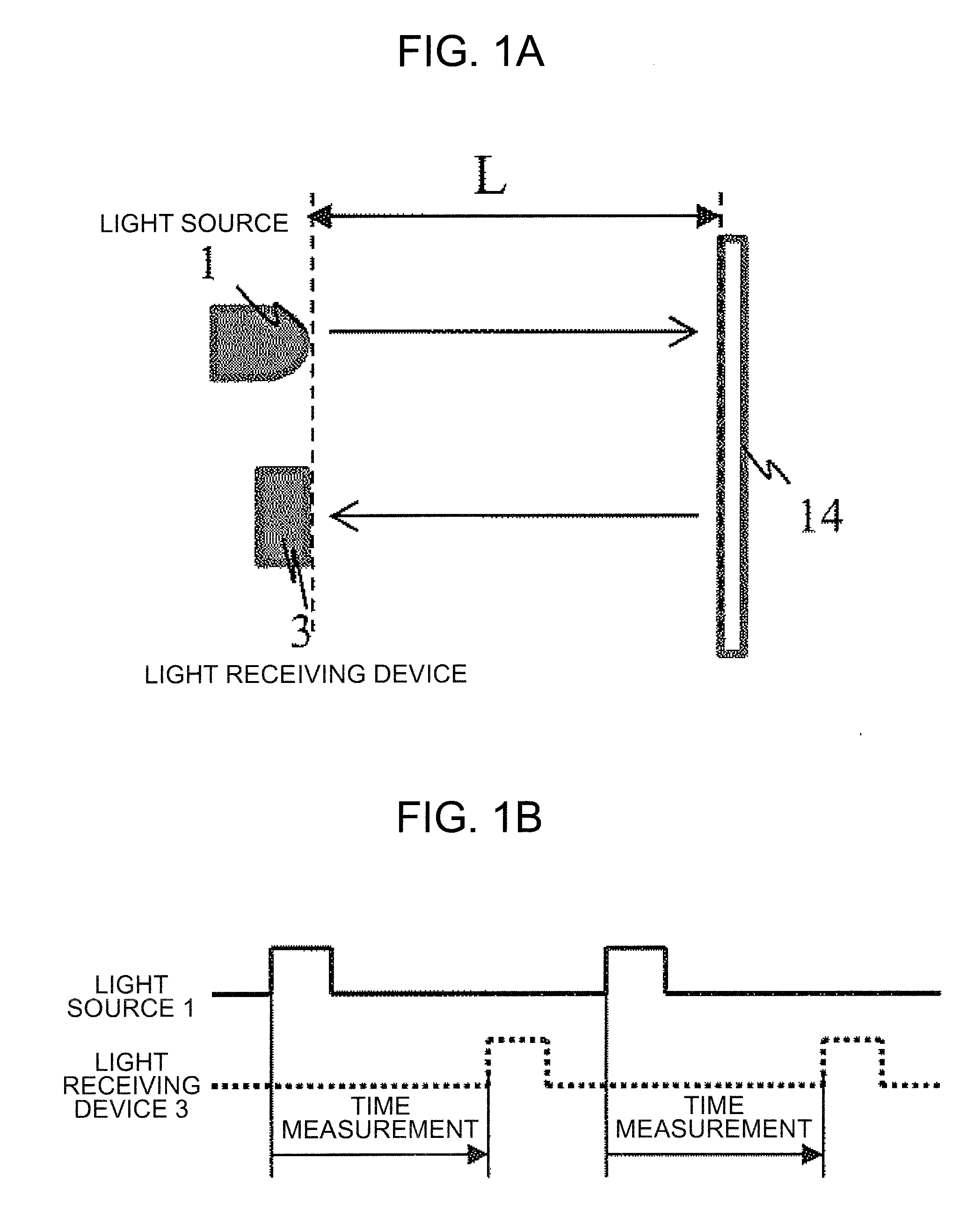
[0026]FIGS. 1A and 1B illustrate the distance measurement principle of the present embodiment. As shown in FIGS. 1 A and 1B, a TOF (Time of Flight) system is described in which a measurement is performed by a difference between an emission time of light from a laser light source 1 and a light receiving time of light in a light receiving device 3 of light reflected from an object 14. Light emitted from the laser light source 1 is irradiated on the object 14. The light irradiated on the object 14 is scattered and part of light is detected by the light receiving device 3. When the time difference is set to t [s], a distance L [m] is represented by the following formula (1) on the basis of a velocity of light 3.0×10⁸ [m].
L[m]=velocity of light 3.0×10⁸[m]×t[s] / 2 (1)
[0027]By calculating a distance in accordance with the above-described formula (1), the optical distance measuring apparatus is realized.
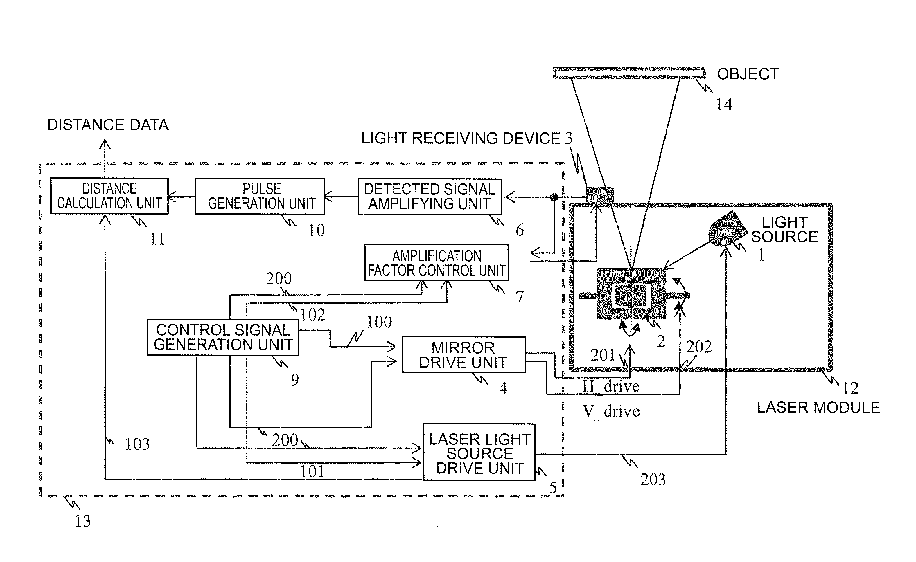
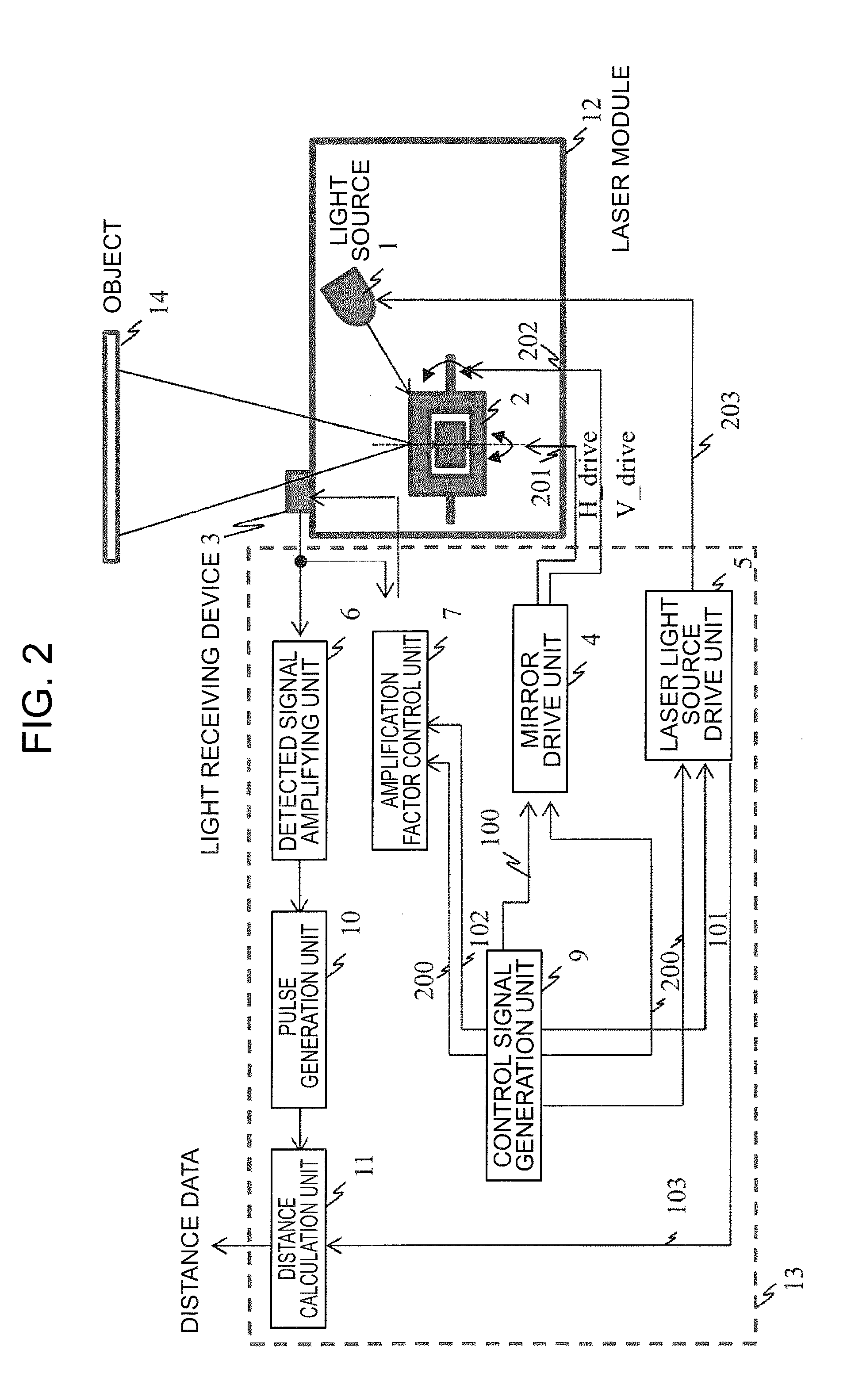
[0028]Next, referring to FIG. 2, a configuration of the optical distance measuring appa...
second embodiment
[0063]A second embodiment of the present invention will be described with reference to FIG. 12. The present embodiment differs from the first embodiment, and intensity of the light source 1 is controlled and a light reception level of the light receiving device 3 is adjusted.
[0064]FIG. 12 illustrates a configuration of the second embodiment. The second embodiment differs from the first embodiment in that a laser intensity control signal 104 being an output from the amplification factor control unit 7 is input to the laser light source drive unit 5. Hereinafter, a configuration of the amplification factor control unit 7 of the second embodiment will be described with reference to FIG. 13.
[0065]FIG. 13 illustrates a configuration of the amplification factor control unit 7 of the second embodiment. The second embodiment differs from the first embodiment in that a laser intensity control unit 74 is added. The laser intensity control unit 74 generates a signal for actuating the laser lig...
PUM
 Abstract
Description
Claims
Application Information