Collimator and optical isolator with collimator

a collimator and collimator technology, applied in the direction of instruments, polarising elements, soldering apparatus, etc., can solve the problems of destroying the collimator or the laser oscillator itsel

Active Publication Date: 2014-10-09
FURUUCHI KAGAKU
View PDF11 Cites 13 Cited by
  • Summary
  • Abstract
  • Description
  • Claims
  • Application Information

AI Technical Summary

Benefits of technology

[0025]As is described in previous section, some amount of light is reflected without absorbed into the processing workpiece. The reflected light energy is completely isolated with the optical isolator and the triple fiber collimator of this invention from the first fiber and the laser oscillator. The reflected light energy is led with the second and the third fibers to the high temperature durable tube and changed to thermal energy. The reflected light energy thus gives no damages to the laser oscillator and the transmitting fiber.

Problems solved by technology

Or, otherwise, the thermal energy will heat the fiber, surrounding polymer material, ferrule, or the inner wall of the optical isolator and result in destroying the collimator or the laser oscillator itself, at last end.

Method used


Image

  • Collimator and optical isolator with collimator
  • Collimator and optical isolator with collimator
  • Collimator and optical isolator with collimator

Examples


working example

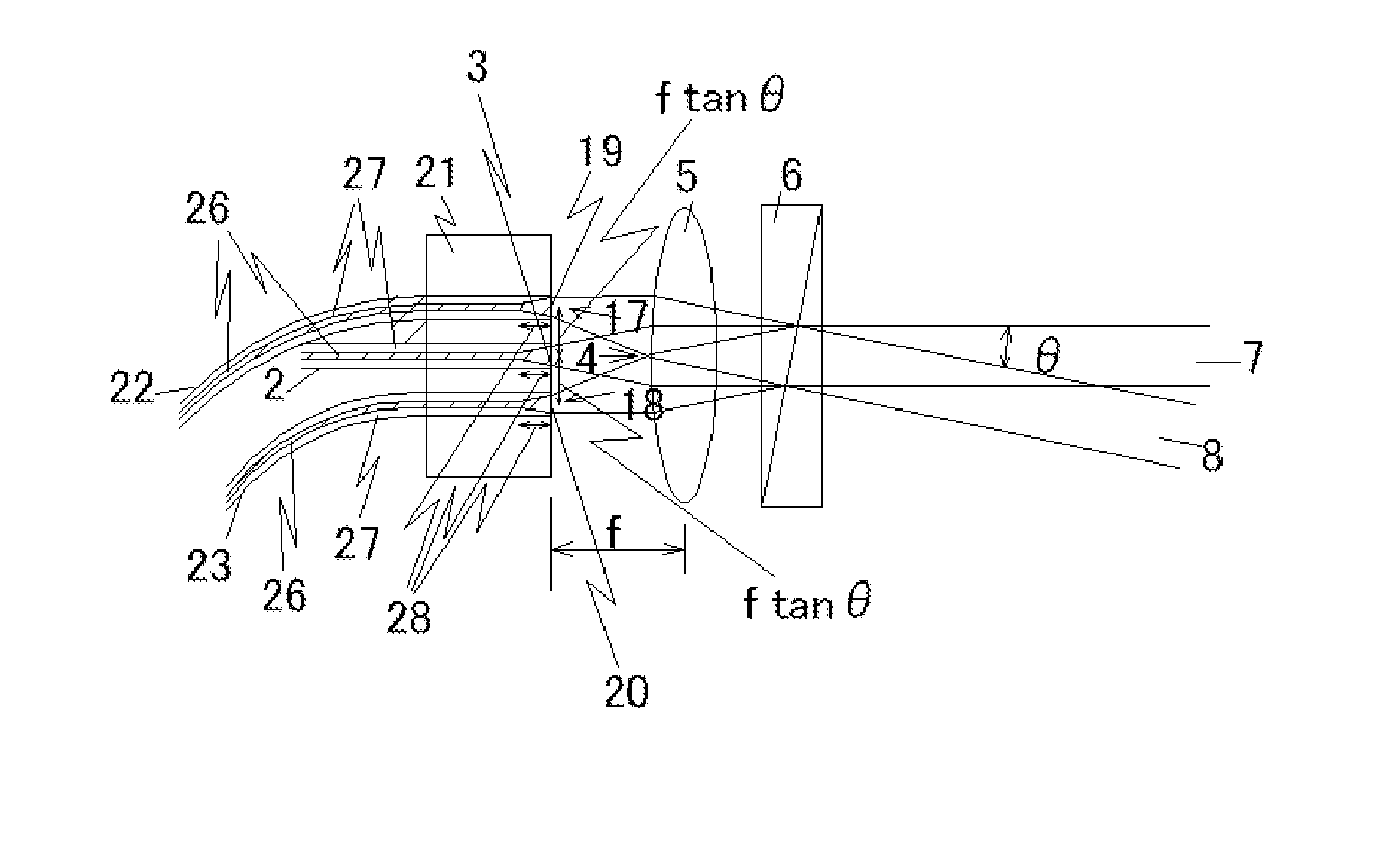
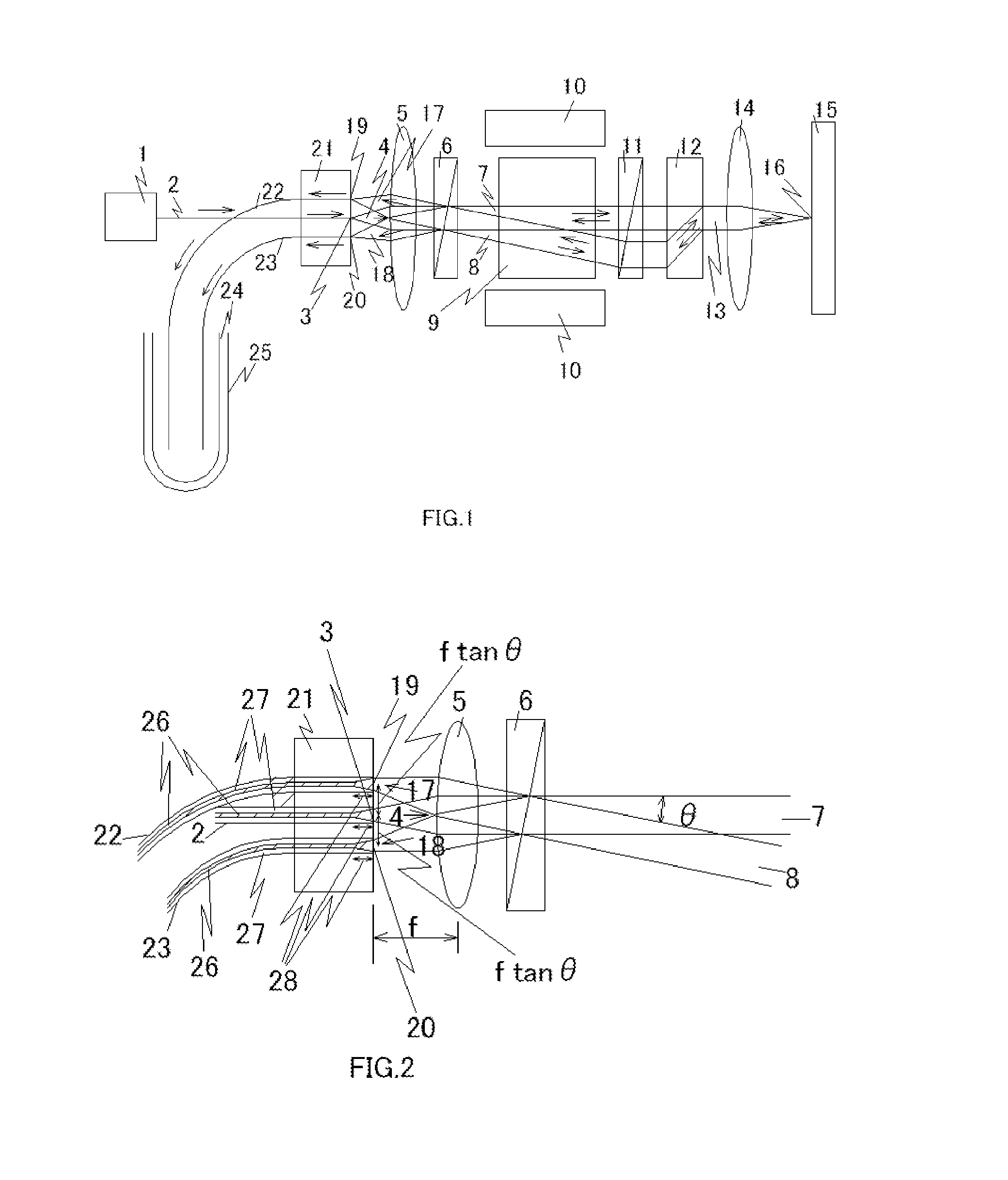
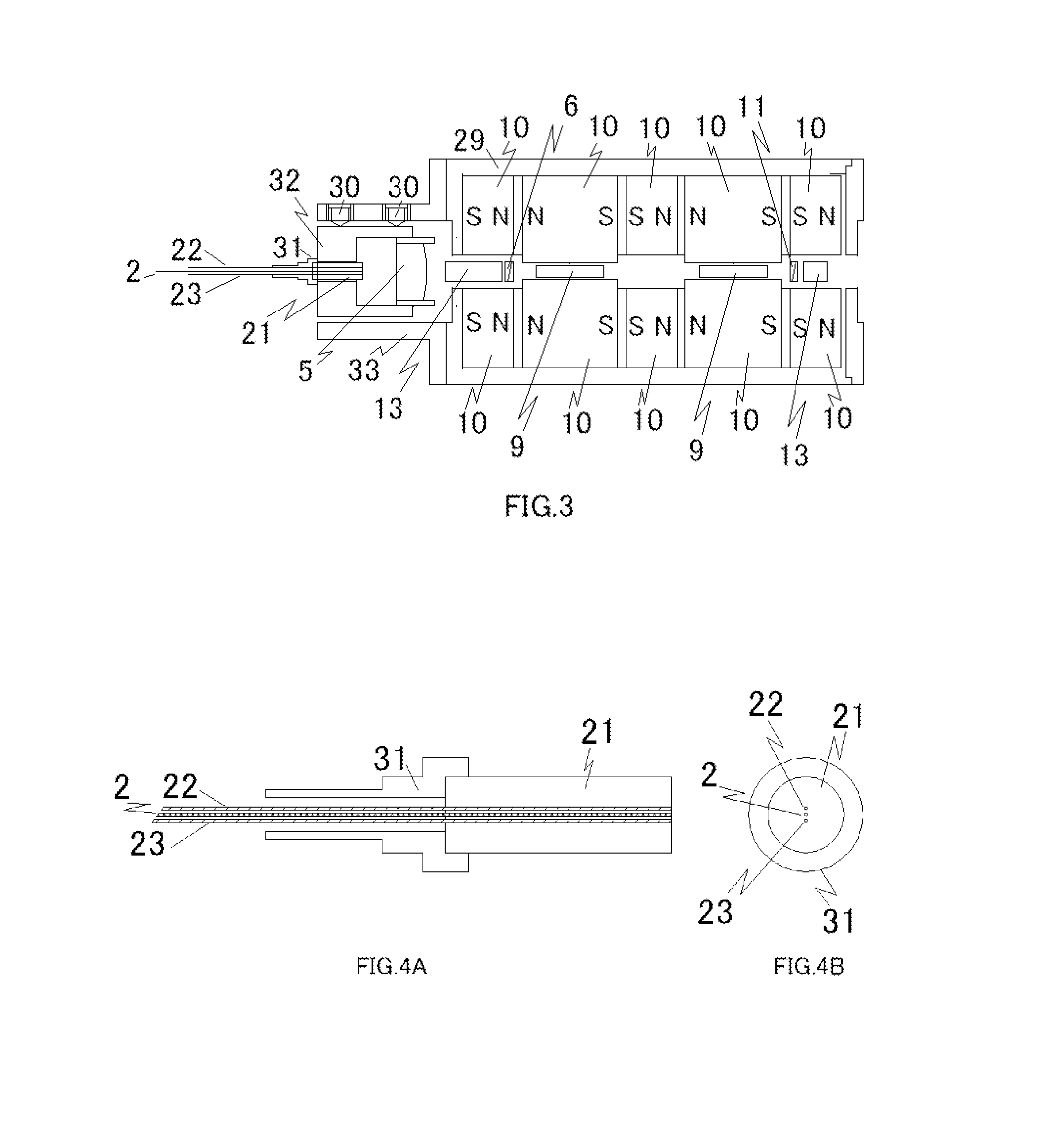
[0032]FIG. 3 shows the cross section of an embodiment of this invention. A collimator composed of a three core zirconia ferrule with three fibers and a lens 5 is combined with an optical isolator whose polarizers 6 and 11 are Rochon prisms as a kind of wedge polarizer.

[0033]FIGS. 4A and 4B show details of the collimator. Three fibers 2, 22, and 23 are fixed in the three holes of the zirconia ferrule 21 mounted on plug 31. The first fiber 2 has a clad diameter of 125 micrometers. The core diameter of the end of the first fiber is expanded from initial 10 micrometer to 20 micrometers. The numerical aperture NA of this core expanded fiber is 0.05. The core diameter of both the second fiber 22 and the third fiber 23 is 62.5 micrometers and the clad diameter is 125 micrometers. The core diameter of the second and the third fibers is larger than the core diameter of the first fiber so as to receive the return light easily. Zirconia ferrule with 2.5 mm diameter has a hole with 125 micromet...


PUM

PropertyMeasurementUnit
angleaaaaaaaaaa
wavelengthaaaaaaaaaa

Abstract

An optical isolator with a collimator which is used at the tip end of a laser beam transmitting fiber utilized in a laser processing. The optical isolator can provide solutions to the problems how to make return lights to be isolated from an incident light path and how to prevent the light energy from being conducted to an incident fiber, a laser oscillator, the collimator, and the optical isolator. The solutions comprise light-receiving fibers (22 and 23) disposed at focal points of a collimator lens (5) to which reflected lights from a workpiece return through the optical isolator. The return lights are then led to a ceramic tube (24) where the return light energy is converted to thermal energy and dissipated.

Description

FIELD OF THE INVENTION[0001]This invention relates to an optical isolators with an optical collimators which is set at the tip end of a light transmitting fibers conveying a fiber laser light energy to a workpiece to be processed by, for example, cutting, marking or soldering. This optical isolator with the optical collimators is used to prevent return lights reflected from the object from entering into the light transmitting fiber and a laser light source.BACKGROUND OF THE INVENTION[0002]Solid-state YAG lasers were previously used for a laser welding, cutting, or marking of metals in metal processing. Fiber lasers were recently developed and begun to be used practically in the wavelength region between 1.0 micrometer and 1.1 micrometers. The fiber lasers are paid attention as a replacement of YAG lasers.[0003]Optical reflectivity of metals is very high in these wavelength regions, especially the optical reflectivity of gold, silver, copper, and aluminum are more than 90%. Although ...

Claims


Application Information

Patent Timeline
Patent Type & Authority Applications(United States)
IPC IPC(8): G02F1/09B23K26/064G02B6/32G02B27/28
CPCG02F1/093B23K26/08B23K26/38G02B6/2746B23K1/0056B23K26/0648B23K26/064B23K26/21B23K26/20
Inventor HOSOKAWA, TADATOSHI
Owner FURUUCHI KAGAKU
Why Eureka
Try Eureka