

Cross flow fan
a technology of cross-flow fan and air conditioning device, which is applied in the direction of lighting and heating equipment, liquid fuel engines, heating types, etc., can solve the problems of increased power loss caused by fans, increased difficulty in air flow along flow paths, and increased air flow turbulence, so as to reduce the decrease of the flow path width, suppress the lowering of the blowing performance of the fan, and reduce the change of air speed
- Summary
- Abstract
- Description
- Claims
- Application Information
AI Technical Summary
Benefits of technology
Problems solved by technology
Method used
Image

Examples
embodiment 1
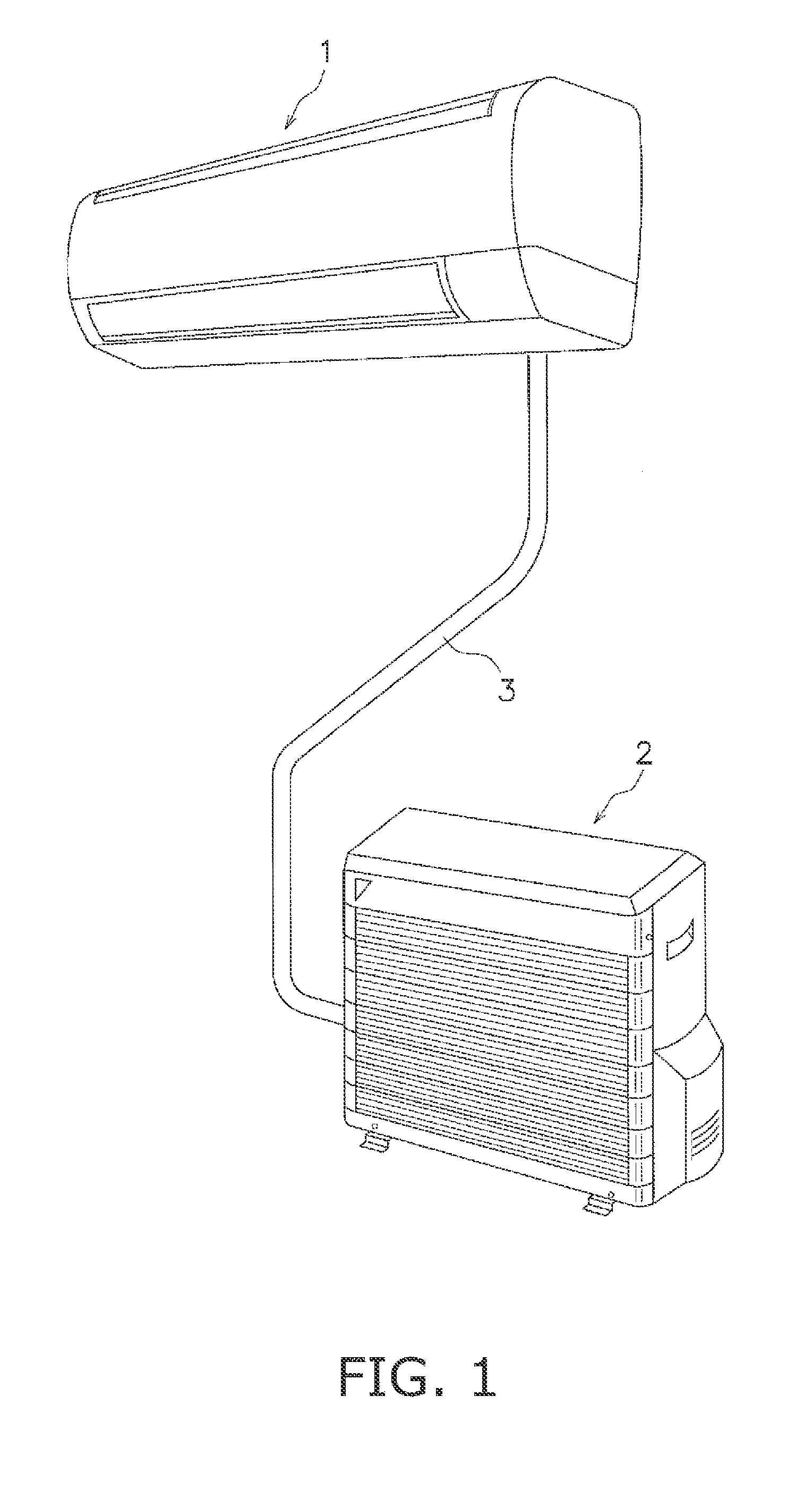
[0039]FIG. 1 shows the external appearance of an air conditioning apparatus equipped with a cross flow fan that is an embodiment of the present invention.
[0040]The air conditioning apparatus is an apparatus for supplying conditioned air to a room. The air conditioning apparatus is equipped with an indoor unit 1, which is attached to a wall surface or the like in a room, and an outdoor unit 2, which is installed outdoors.
[0041]An indoor heat exchanger is housed in the indoor unit 1, and an outdoor heat exchanger not shown in the drawings is housed in the outdoor unit 2. Furthermore, the indoor heat exchanger and the outdoor heat exchanger are interconnected by a refrigerant pipe 3 to configure a refrigerant circuit.
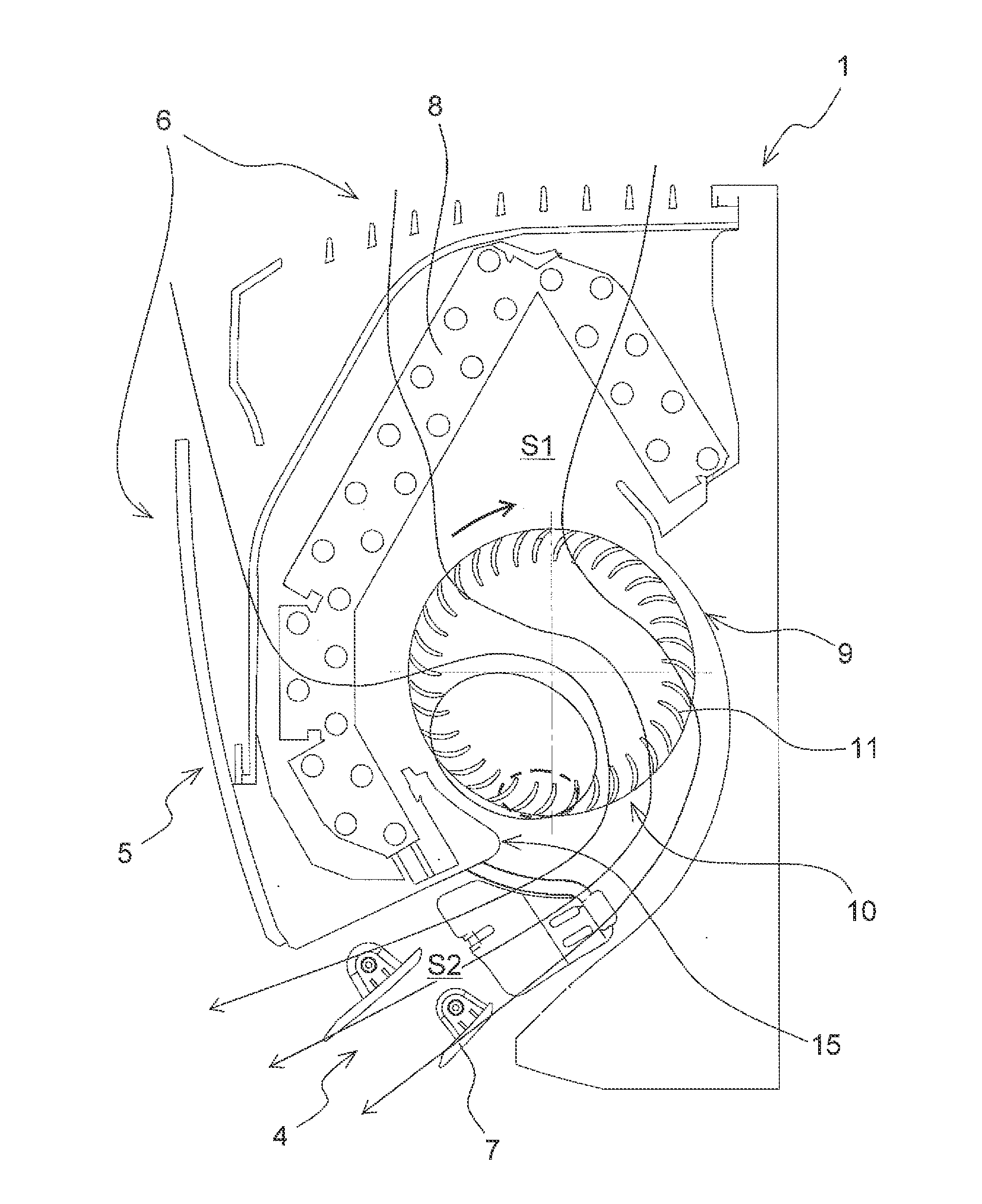
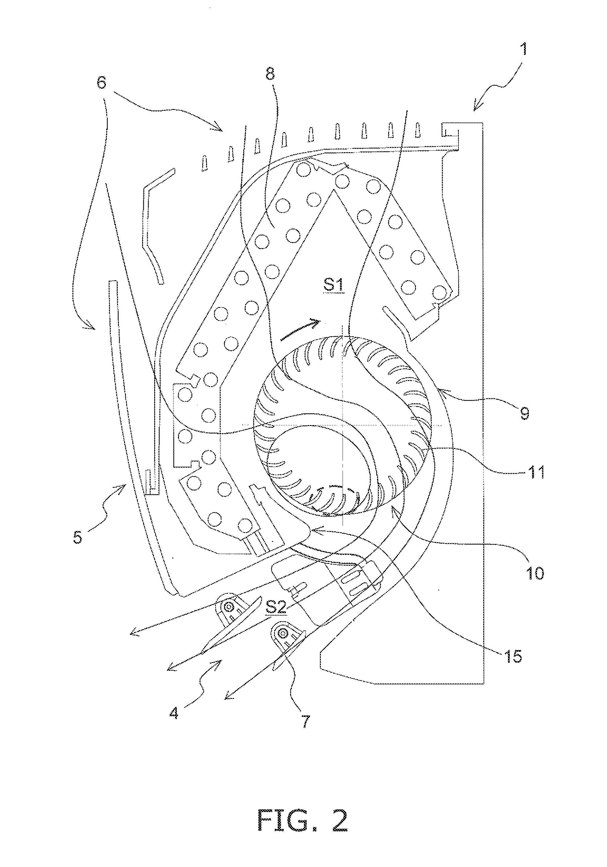
[0042]The indoor unit 1, which is shown in FIG. 2, is a wall-mounted indoor unit attached to a wall surface or the like in a room and is mainly equipped with an indoor unit casing 5, an indoor heat exchanger 8, and a cross flow fan 10.
[0043]The indoor heat exchanger 8 and ...
embodiment 2
[0056]As shown in FIG. 8, in a blade 200 pertaining to embodiment 2, the pressure surface arc Rp is configured by two arcs. The pressure surface arc Rp is configured by a first pressure surface arc Rp1 positioned on the inner peripheral side and a second pressure surface arc Rp2 positioned on the outer peripheral side; a radius rp1 of the first pressure surface arc Rp1 positioned on the inner peripheral side and a radius rp2 of the second pressure surface arc Rp2 positioned on the outer peripheral side are each greater than the radius rs of the suction surface arc Rs; and the radius rp1 of the first pressure surface arc Rp1 positioned on the inner peripheral side is smaller than the radius rp2 of the second pressure surface arc Rp2 positioned on the outer peripheral side. That is, ri>ro and rp2>rpi>rs. Furthermore, a region of maximum thickness of the blade is located in a position 40% to 60% from the inner peripheral side arc Ri in the lengthwise direction. The blades 200 are dispo...
embodiment 3
[0058]As shown in FIG. 10, in a blade 300 pertaining to embodiment 3, the pressure surface arc Rp is configured by three arcs. The pressure surface arc Rp is configured by a first pressure surface arc Rp1 positioned on the inner peripheral side, a third pressure surface arc Rp3 positioned on the outer peripheral side, and a second pressure surface arc Rp2 positioned between the inner peripheral side and the outer peripheral side; a radius rp1 of the first pressure surface arc Rp1 positioned on the inner peripheral side, a radius rp2 of the second pressure surface arc Rp2 positioned between the inner peripheral side and the outer peripheral side, and a radius rp3 of the third pressure surface arc Rp3 positioned on the outer peripheral side are each greater than the radius rs of the suction surface arc Rs; the radius rp1 of the first pressure surface arc Rp1 positioned on the inner peripheral side is smaller than the radius rp3 of the third pressure surface arc Rp3 positioned on the o...
PUM
 Abstract
Description
Claims
Application Information