Method for manufacturing glass-fine-particle-deposited body and method for manufacturing glass base material
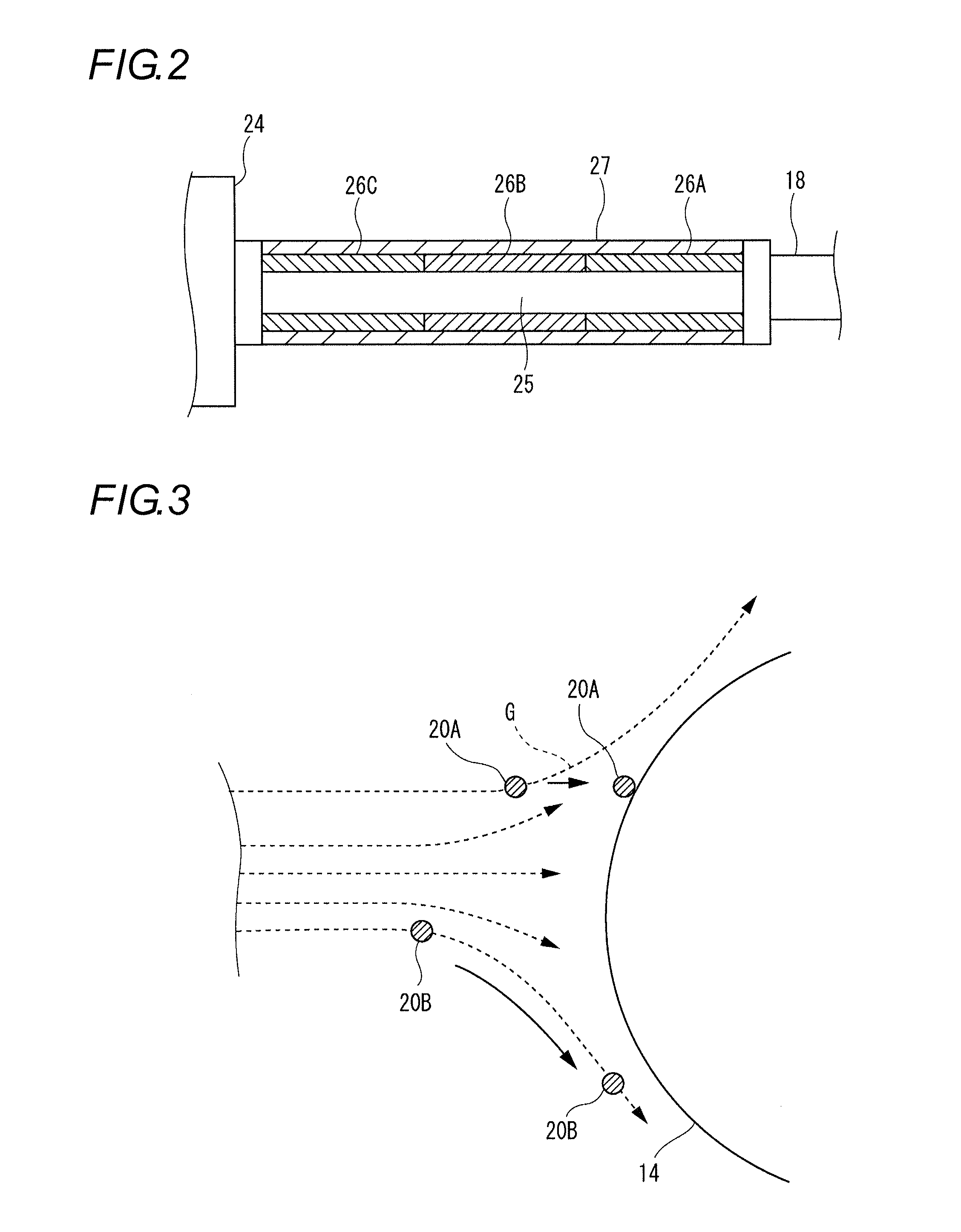
a technology of glass base material and glass fine particles, which is applied in the direction of glass making apparatus, glass deposition burners, manufacturing tools, etc., can solve the problems of limited ratio of the deposited amount of glass fine particles to the supplied amount of glass source material gas, and the difficulty of adhesion of produced glass fine particles to the starting rod or the glass-fine particle-deposited body, so as to improve the adhesion efficiency of glass fine particles on the starting rod and the glass-fine particle-
- Summary
- Abstract
- Description
- Claims
- Application Information
AI Technical Summary
Benefits of technology
Problems solved by technology
Method used
Image
Examples
first embodiment
[0040]The following describes the methods for manufacturing a glass-fine-particle-deposited body and a glass base material as the first embodiment of the invention with reference to the drawings. Incidentally, explanation is made using the VAD method as an example in the following but the invention is not limited to the VAD method. It is also possible to apply the invention to other methods for manufacturing a glass-fine-particle-deposited body, such as the OVD method and the MMD method.
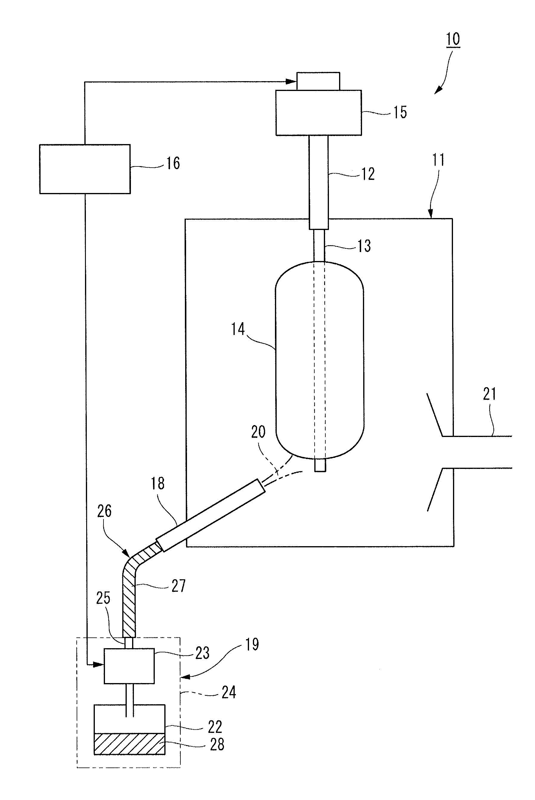
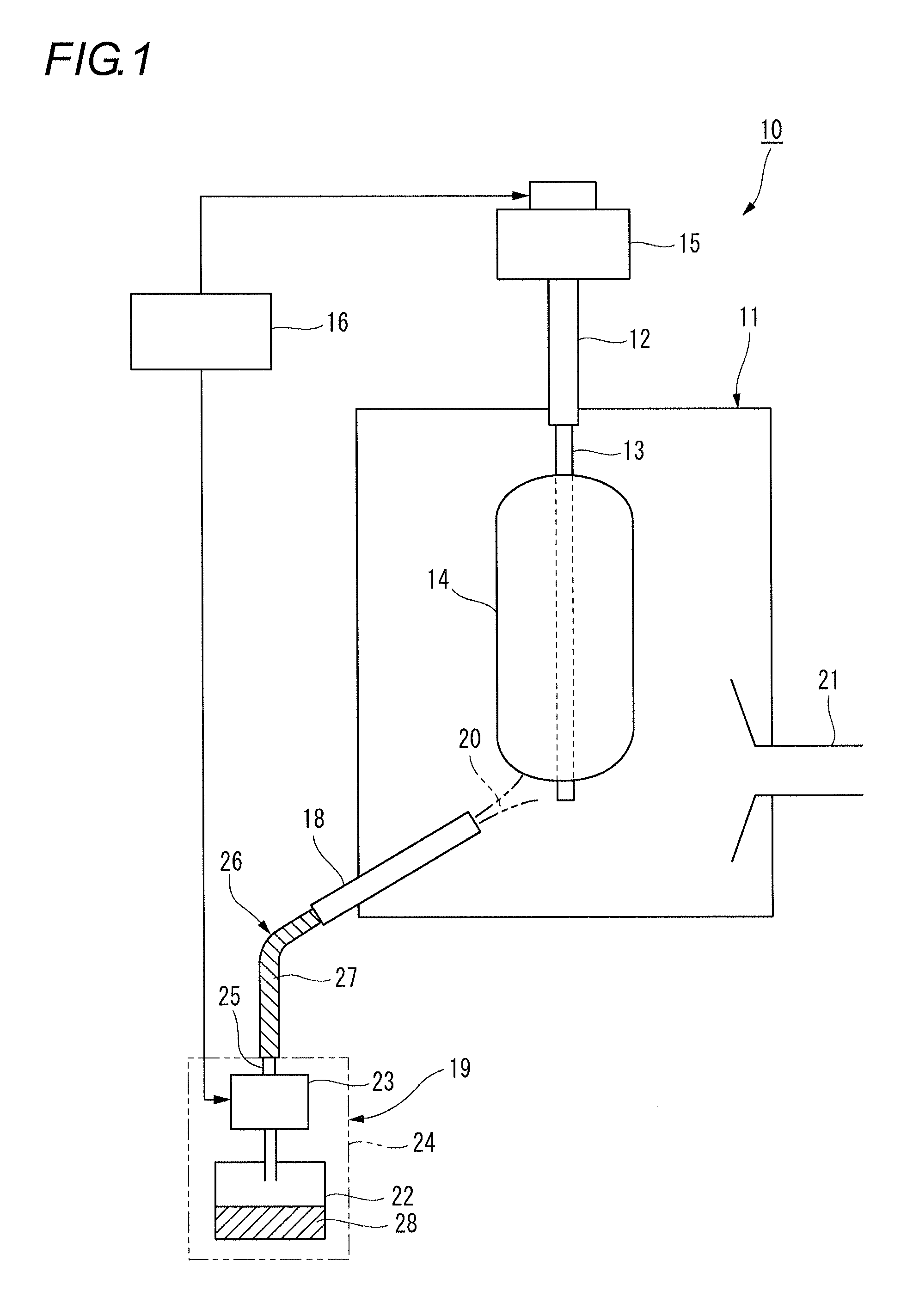
[0041]As shown in FIG. 1, a manufacturing equipment 10 for carrying out the method for manufacturing a glass-fine-particle-deposited body according to the present embodiment is one for depositing glass fine particles by the VAD method, a supporting rod 12 is suspended inside a reaction container 11 from the above, and a starting rod 13 is attached to the lower end of the supporting rod 12. An exhaust pipe 21 is attached to a side face of the reaction container 11.
[0042]The supporting rod 12 is held a...
example a
[0065]Next, one Example of the method for manufacturing a glass base material of the invention is described.
[0066]In both of Example and Comparative Example, the glass base material is manufactured using the following materials.[0067]Starting rod: quartz glass having a diameter of 25 mm and a length of 1,000 mm[0068]Gases charged into burner for cladding: Source material gas . . . SiCl4 (1 to 7 SLM), Flame forming gases . . . H2 (100 to 150 SLM), O2 (100 to 150 SLM), Burner sealing gas . . . N2 (20 to 30 SLM)
[0069]Deposition of glass fine particles is performed by the VAD method. After the resulting glass-fine-particle-deposited body is heated to 1,100° C. in a mixed atmosphere of an inert gas and chlorine gas, it is heated to 1,550° C. in an He atmosphere to impart transparency.
[0070]The temperature of outer circumference of the gas supplying pipe was measured at three points along a longitudinal direction of the pipe, and the minimum temperature gradient: T (° C. / m) between the me...
second embodiment
[0074]The following describes methods for manufacturing a glass-fine-particle-deposited body and a glass base material as the second embodiment with reference to Drawings. Since the equipment configuration in the second embodiment is the same as in the first embodiment (FIG. 1), detailed explanations of the equipment configuration, controlling methods, and the like are omitted. For the numbers of devices in the following description, FIG. 1 is referred to.
[0075]In the method for manufacturing a glass base material of the present embodiment, at least a part of the gas supplying pipe 25 from the temperature controlled booth 24 to the burner 18 for cladding is controlled to a temperature of 100° C. or higher by the tape heater 26 that is a heating element and also the Reynolds number Re of the source material gas flowing in the gas supplying pipe 25 from the source material container 22 to the burner 18 for cladding is controlled to 2,000 or more. In general, the gas flow flowing in th...
PUM
| Property | Measurement | Unit |
|---|---|---|
| temperature | aaaaa | aaaaa |
| particle diameter | aaaaa | aaaaa |
| heat-resistant temperature | aaaaa | aaaaa |
Abstract
Description
Claims
Application Information
 - R&D
- Intellectual Property
- Life Sciences
- Materials
- Tech Scout
- Unparalleled Data Quality
- Higher Quality Content
- 60% Fewer Hallucinations
Browse by: Latest US Patents, China's latest patents, Technical Efficacy Thesaurus, Application Domain, Technology Topic, Popular Technical Reports.
© 2025 PatSnap. All rights reserved.Legal|Privacy policy|Modern Slavery Act Transparency Statement|Sitemap|About US| Contact US: help@patsnap.com


