Motor control apparatus with power failure determination unit

a technology of power failure determination and motor control, which is applied in the direction of motor/generator/converter stopper, dynamo-electric converter control, dc motor stopper, etc., can solve problems such as power failure at the ac power supply side, damage and deformation, and difficulty in continuing normal operation of the motor

Active Publication Date: 2014-10-16
FANUC LTD
View PDF5 Cites 18 Cited by
  • Summary
  • Abstract
  • Description
  • Claims
  • Application Information

AI Technical Summary

Benefits of technology

[0016]In a second aspect, the motor control apparatus according to the first aspect described above further includes: a DC voltage detection unit for detecting a DC voltage value at the DC link; a voltage loop control unit for generating a current command to be input to the current loop control unit based on an error between an input DC voltage command and the DC voltage value; and a voltage loop saturation state determination unit for determining to be in a voltage loop saturation state when a magnitude of the current command is equal to or larger than a predetermined current prescribed value. The power failure determination unit determines that a power failure has occurred at the AC power supply side of the PWM rectifier by using the first requirement described above, the second requirement described above, and a third requirement that the voltage loop saturation state determination unit determines to be in the voltage loop saturation state.
[0017]In a third aspect, the motor control apparatus according to the first aspect described above further includes a current amplitude calculation unit for calculating a current amplitude value from the AC current value. The power failure determination unit determines that a power failure has occurred at the AC power supply side of the PWM rectifier by using the first requirement described above, the second requirement described above, and a fourth requirement that the current amplitude value is equal to or less than a predetermined amplitude value.
[0018]In a fourth aspect, the motor control apparatus according to the second aspect described above further includes a current amplitude calculation unit for calculating a current amplitude value from the AC current value. The power failure determination unit determines that a power failure has occurred at the AC power supply side of the PWM rectifier by using the first requirement described above, the second requirement described above, the third requirement described above, and a fourth requirement that the current amplitude value is equal to or less than a predetermined amplitude value.
[0019]In a fifth aspect, the motor control apparatus according to the first to fourth aspects described above further includes a voltage amplitude calculation unit for calculating a voltage amplitude value from the AC voltage value detected by the voltage amplitude detection unit. The power failure determination unit determines that a power failure has occurred at the AC power supply side of the PWM rectifier also when the voltage amplitude value is equal to or less than a predetermined amplitude value.

Problems solved by technology

In such a motor control apparatus, when an input power supply voltage decreases due to power failure at an AC power supply side of a rectifier, it is difficult to continue a normal operation of the motor.
Therefore, faults such as damage and deformation may occur to: the motor; a motor control apparatus for driving the motor; a tool connected to the motor driven by the motor control apparatus; a processing target to be processed by the tool; a manufacturing line with the motor control apparatus; and the like.
However, in a case that a PWM rectifier is applied to a rectifier described in Japanese Laid-open Patent Publication No. 2006-14546, a power failure at an AC power supply side may not be detected in the method described above during a regenerative operation in which a DC output voltage does not decrease since the DC output voltage appears as an input voltage through the rectifier circuit, when a power failure has occurred at the AC power supply side of the PWM rectifier which is an open state. FIG. 10 is a diagram illustrating a power failure detection at an AC power supply side of a PWM rectifier during a regenerative operation in which a DC output voltage does not decrease, in a motor control apparatus with a conventional PWM rectifier and an inverter.
Therefore, there is a drawback that a power failure can be stably detected only when there are no LC filters.
Furthermore, according to an invention described in Japanese Laid-open Patent Publication No. 2009-44781, it is not possible to detect a power failure when a power failure occurs during a regenerative operation since there is no possibility that a voltage command value decreases.

Method used


Image

  • Motor control apparatus with power failure determination unit
  • Motor control apparatus with power failure determination unit
  • Motor control apparatus with power failure determination unit

Examples


first embodiment

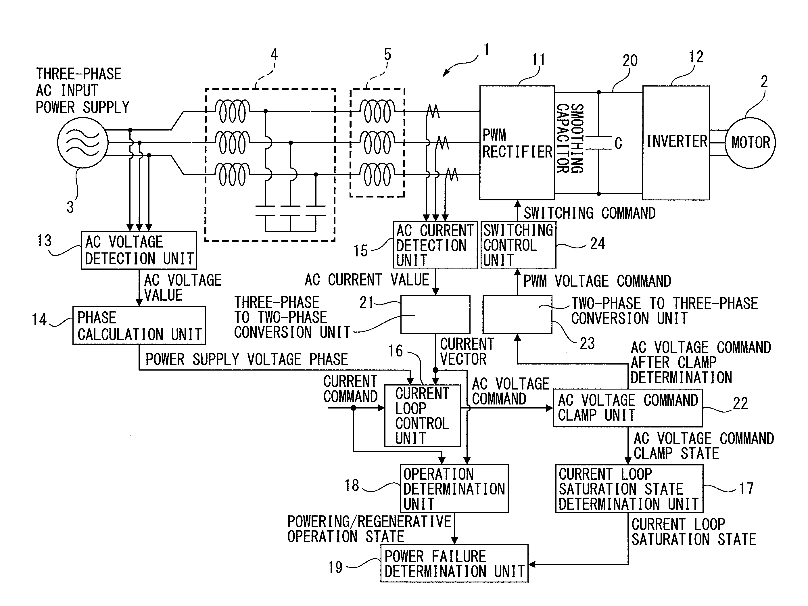
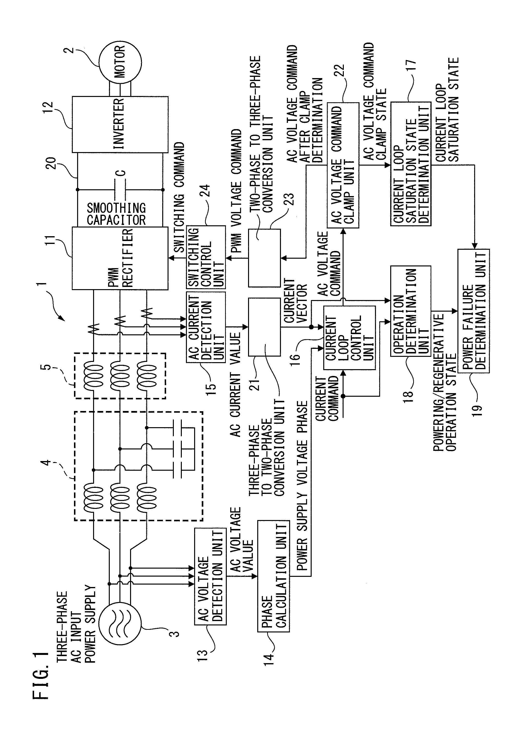
[0032]FIG. 1 is a principle block diagram illustrating a motor control apparatus according to a Hereinafter, components with the same reference numerals in different drawings denote those having the same function.

[0033]According to a first embodiment, a motor control apparatus 1 includes a PWM rectifier 11, an inverter 12, an AC voltage detection unit 13, a phase calculation unit 14, an AC current detection unit 15, a current loop control unit 16, a current loop saturation state determination unit 17, an operation determination unit 18, and a power failure determination unit 19.

[0034]The PWM rectifier 11 is configured as a bridge circuit of semiconductor switching elements and performs a bidirectional power conversion between AC power at an AC power supply side provided with a commercial three-phase AC power supply 3 and DC power at a DC link being a DC side. LC filters 4 and AC reactors 5 are connected to the AC power supply side of the PWM rectifier 11.

[0035]The PWM rectifier 11 ...

second embodiment

[0072]Since the power failure determination unit determines that a power failure has occurred at the AC power supply side of the PWM rectifier when the operation determination unit determines to be in the regenerative operation state, the current loop saturation state determination unit determines to be in the current loop saturation state, and the voltage loop saturation state determination unit determines to be in the voltage loop saturation state, it is possible to more accurately detect a power failure when the power failure occurs in which the AC power supply side becomes the open state while the PWM rectifier is in the regenerative operation.

third embodiment

[0073]Since the power failure determination unit determines that a power failure has occurred at the AC power supply side of the PWM rectifier when the operation determination unit determines to be in the regenerative operation state, the current loop saturation state determination unit determines to be in the current loop saturation state, and a current amplitude value calculated by the current amplitude calculation unit is equal to or less than the predetermined amplitude value, it is possible to eliminate an erroneous determination that a power failure has occurred at the AC power supply side when power regenerated by the PWM rectifier becomes excessive, thus makes it possible to even more accurately detect a power failure in which the AC power supply side is the open state while the PWM rectifier is in the regenerative operation.


PUM


Abstract

A motor control apparatus includes: a PWM rectifier; an inverter; a detection unit for detecting an AC voltage value of the PWM rectifier; a calculation unit for calculating a power supply voltage phase; a detection unit for detecting an AC current value of the PWM rectifier; a current loop control unit for generating an AC voltage command to control a power conversion operation of the PWM rectifier; a current loop saturation state determination unit for determining to be in a current loop saturation state when a magnitude of the AC voltage command is equal to or larger than a predetermined voltage prescribed value; an operation determination unit for determining whether the PWM rectifier is in a powering operation or in a regenerative operation and a power failure determination unit for determining a presence or absence of a power failure at the AC power supply side from the determination results.

Description

BACKGROUND OF THE INVENTION[0001]1. Field of the Invention[0002]The present invention relates to a motor control apparatus in which AC power supplied from an AC power supply side is converted to DC power to be output, and then the converted DC power is further converted to AC power for driving a motor in order to supply the power to the motor. More particularly, the invention relates to the motor control apparatus with a power failure determination unit for determining presence or absence of a power failure at the AC power supply side.[0003]2. Description of the Related Art[0004]In a motor control apparatus for driving motors used in machine tools, forming machines, injection molding machines, industrial machines, or various kinds of robots, DC power temporarily converted from AC power which is input from an AC power supply side is further converted to AC power. The converted AC power is used as drive power for a motor provided for each of drive axis. The motor control apparatus inc...

Claims


Application Information

Patent Timeline
Patent Type & Authority Applications(United States)
IPC IPC(8): H02P27/08
CPCH02P27/08H02P3/14H02P27/06H02P29/025
Inventor YAMAMOTO, KENTA
Owner FANUC LTD
Why Eureka
Try Eureka