Motor vehicle having traction motor

Inactive Publication Date: 2014-10-16
TOYOTA JIDOSHA KK +1
View PDF4 Cites 20 Cited by
  • Summary
  • Abstract
  • Description
  • Claims
  • Application Information

AI Technical Summary

Benefits of technology

The invention is a traction motor-equipped motor vehicle that has a discharge device for appropriately operating according to different situations. The vehicle includes a control section that receives sensor data that indicates a state of the vehicle and determines whether activation of the discharge device should be prohibited. This allows for the discharge device to operate appropriately based on the vehicle's situation, such as a collision, and prevents unnecessary activation of the discharge device due to other factors such as a decline in battery voltage. The control section may constantly receive and retain sensor data and make a determination based on the sensor data to activate or prohibit the discharge device. This allows for the discharge device to operate appropriately according to the vehicle's situation.

Problems solved by technology

However, it is not always preferable to activate the discharge device in the same manner upon receiving the collision signal.

Method used


Image

  • Motor vehicle having traction motor
  • Motor vehicle having traction motor
  • Motor vehicle having traction motor

Examples


first embodiment

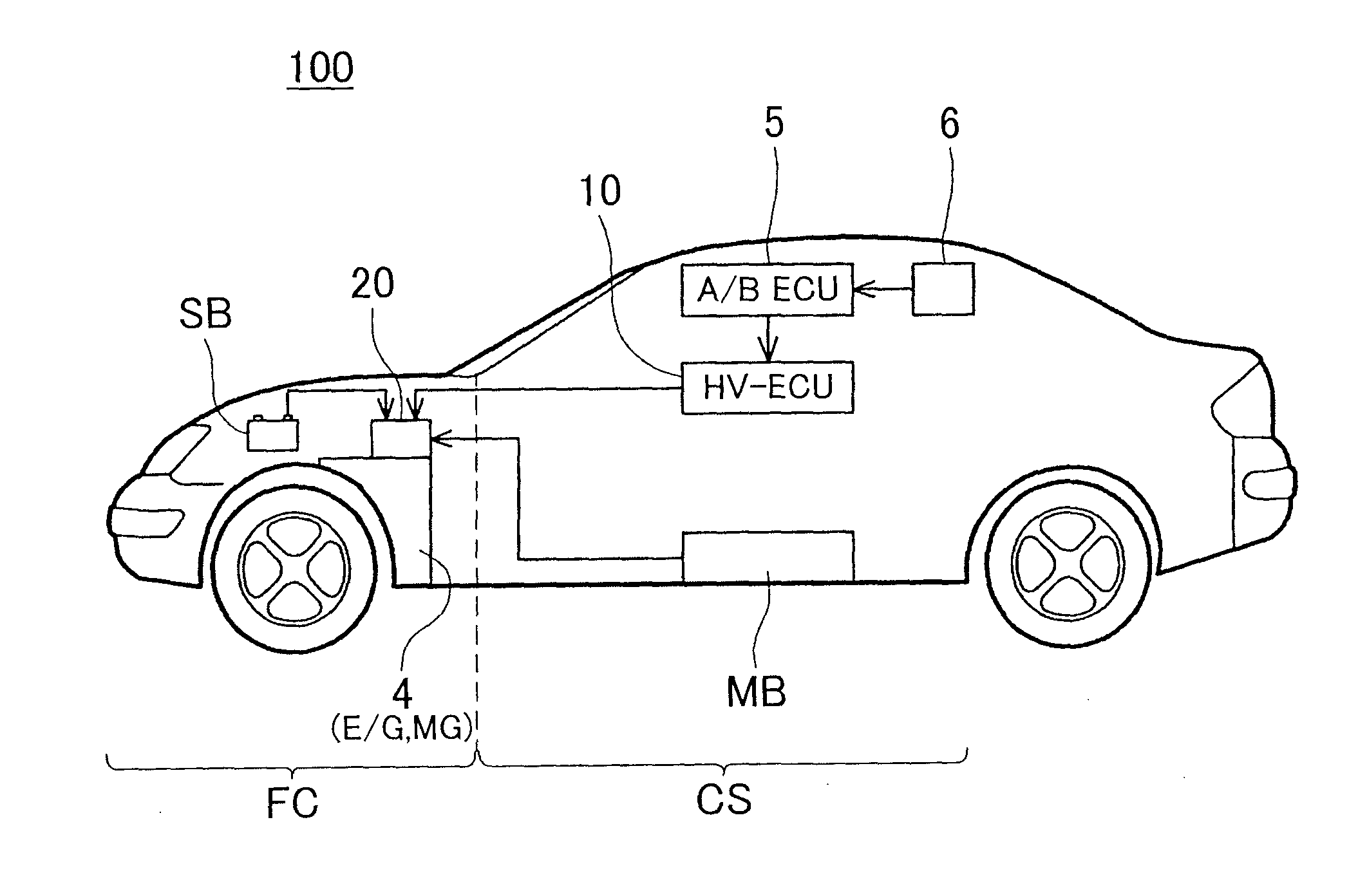
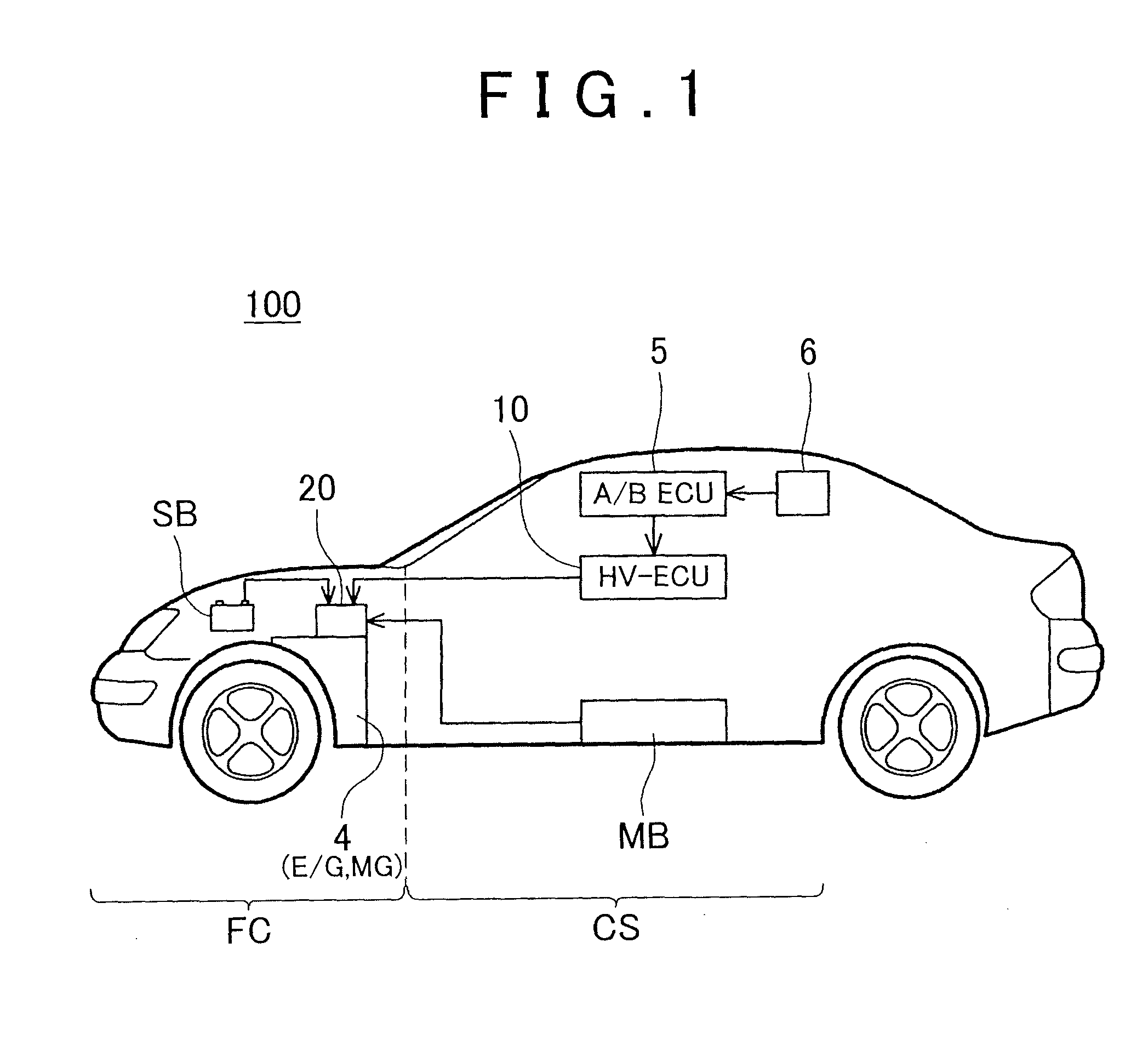
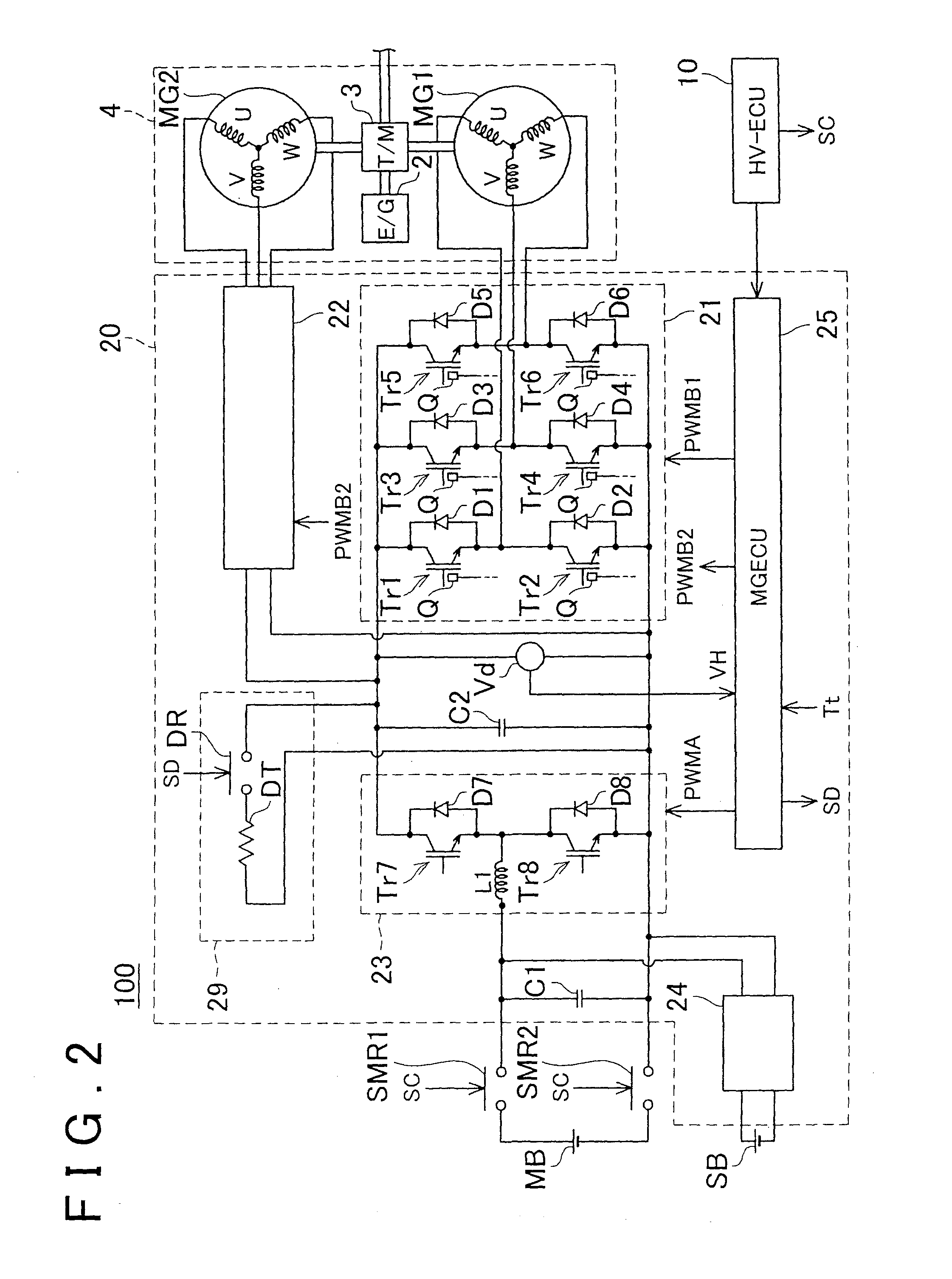
[0029]A motor vehicle in accordance with a first embodiment of the invention will be described with reference to the accompanying drawings. A motor vehicle 100 of the first embodiment is a hybrid vehicle including an engine 2 and two electric motors (MG1 and MG2). FIG. 1 shows a schematic system block diagram of the motor vehicle 100. FIG. 2 shows a control block diagram showing an internal construction of a power controller 20 that controls the two electric motors MG1 and MG2. It is to be noted that the system block diagram of FIG. 1 shows only units related to the invention while various units that the motor vehicle 100 has are omitted from the illustration. Besides, the “power controller” is sometimes termed the power control unit (PCU) as well.

[0030]The power controller 20 converts output voltage of a main battery MB into a voltage suitable for electric motor control, and converts the converted direct-current (DC) power into alternating-current (AC) power, and supplies the conve...

second embodiment

[0046]Next, a second embodiment of the invention will be described. The construction of a motor vehicle in accordance with the second embodiment is the same as that in the first embodiment, and description thereof will be omitted. The motor vehicle of the second embodiment uses the power transistors (Tr1 to Tr6) provided in the inverter and the electric motors MG1 and MG2 as discharge devices. Therefore, a process that the electric motor controller 25 executes upon detection of a collision is different from the process executed in the first embodiment. FIG. 5 shows a flowchart of a process that the electric motor controller 25 executes upon receiving the collision signal (discharge command) from the HV controller 10. Similarly to the first embodiment, the HV controller 10, upon receiving the collision signal from the airbag controller 5, sends a collision signal (discharge command) to the electric motor controller 25, and opens the system main relays SMR1 and SMR2.

[0047]When the pro...

third embodiment

[0050]Next, a vehicle in accordance with a third embodiment of the invention will be described. The hardware construction of the motor vehicle of the third embodiment is basically the same as the hardware construction of the motor vehicles of the first and second embodiments shown in FIGS. 1 and 2. However, in the motor vehicle of the third embodiment, the discharge module 29 has its own controller, and the controller performs various determinations on the basis of signals from other controllers (concretely, the motor controller 25). In the motor vehicle of the third embodiment, the airbag controller 5, the HV controller 10, the electric motor controller 25 and the discharge module (the discharge module's own controller) take their shares of the process related to the discharging. FIG. 6 shows a flowchart of a discharge process in the third embodiment.

[0051]Firstly, the sensor data obtained by the acceleration sensor 6 is sent to the airbag controller 5 (S101). The airbag controller...


PUM


Abstract

A motor vehicle includes an electric motor, a smoothing capacitor, a discharge device and a controller. The smoothing capacitor smoothes the electric current that is used to drive the electric motor. The discharge device is capable of releasing the electric charge stored in the capacitor. The controller is configured to receive sensor data that indicates a state of the motor vehicle and determine whether to activate a discharge device, based on the sensor data received.

Description

BACKGROUND OF THE INVENTION[0001]1. Field of the Invention[0002]The invention relates to a motor vehicle equipped with a traction motor (a vehicle-driving electric motor). Particularly, the invention relates to a hybrid vehicle or an electric motor vehicle. The “motor vehicle” in this specification includes a fuel cell vehicle as well.[0003]2. Description of Related Art[0004]Hybrid vehicles and electric motor vehicles are equipped with an inverter that converts direct current supplied from a battery into alternating current. The inverter that converts electric current is equipped with a capacitor that smoothes electric current (smoothing capacitors) in order to stably output alternating current. Generally, the smoothing capacitor is connected between input terminals of the inverter. Furthermore, some of the hybrid vehicles and electric motor vehicles are equipped with a DC / DC converter that converts the output voltage of the battery into a voltage suitable to be input to the inverte...

Claims


Application Information

Patent Timeline
IPC IPC(8): B60L3/00
CPCY10S903/903B60L3/00B60L3/04B60L2240/12B60L2240/14B60L2240/36B60L2240/525B60L2240/547B60L58/10Y02T10/70
Inventor KANZAKI, TAKAOSAKATA, KOICHISHINDO, YUSUKEIGARASHI, YASUAKI
Owner TOYOTA JIDOSHA KK
Why Eureka
Try Eureka