Controlled rise velocity bouyant ball assisted hydrocarbon lift system and method

Inactive Publication Date: 2014-10-23
SMITHSONIAN ENERGY
View PDF0 Cites 15 Cited by
  • Summary
  • Abstract
  • Description
  • Claims
  • Application Information

AI Technical Summary

Benefits of technology

[0009]A hydrocarbon lift system for lifting petroleum fluid(s) from an enclosed subterranean reservoir to the earth's surface, the system comprises a column of a plurality of buoyant balls in an outer pipe configured to entrain the buoyant balls into a first fluid in an annulus formed with an inner pipe drill string; a pressure differential in the inner pipe drill string with respect to the reservoir via the entrained buoyant balls in a se

Problems solved by technology

The carbon dioxide, natural gas and nitrogen EOR consume much more electric power per barrel of oil produced than thermal EOR methods.
Current electric power require

Method used


Image

  • Controlled rise velocity bouyant ball assisted hydrocarbon lift system and method
  • Controlled rise velocity bouyant ball assisted hydrocarbon lift system and method
  • Controlled rise velocity bouyant ball assisted hydrocarbon lift system and method

Examples


Embodiment Construction

[0020]Reference will now be made to exemplary embodiments illustrated in the drawings and specific language will be used herein to describe the same. It will nevertheless be understood that no limitation of the scope of the disclosure is thereby intended. Alterations and further modifications of the inventive features illustrated herein and additional applications of the principles of the inventions as illustrated herein, which would occur to one skilled in the relevant art and having possession of this disclosure, are to be considered within the scope of the invention.

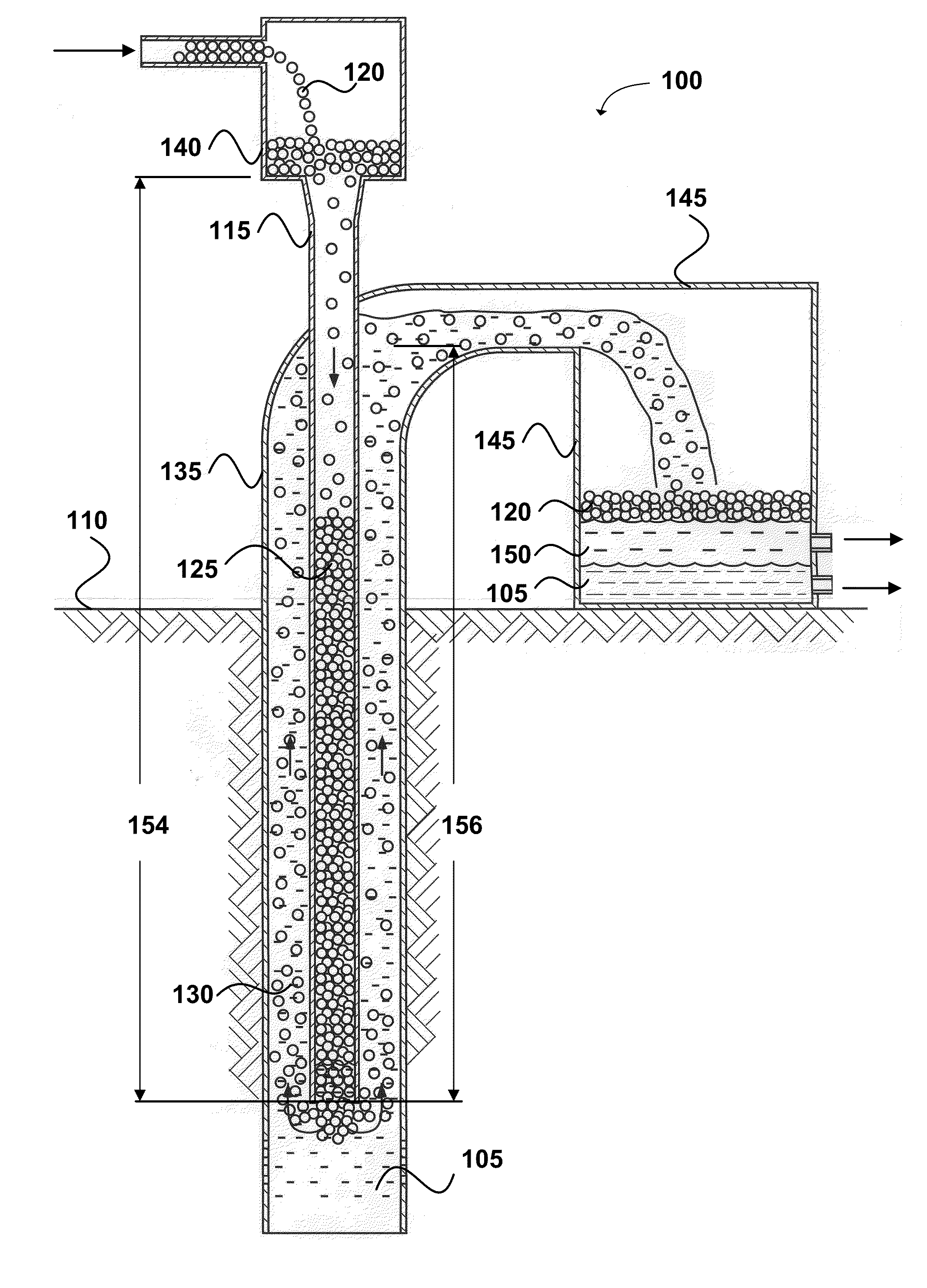
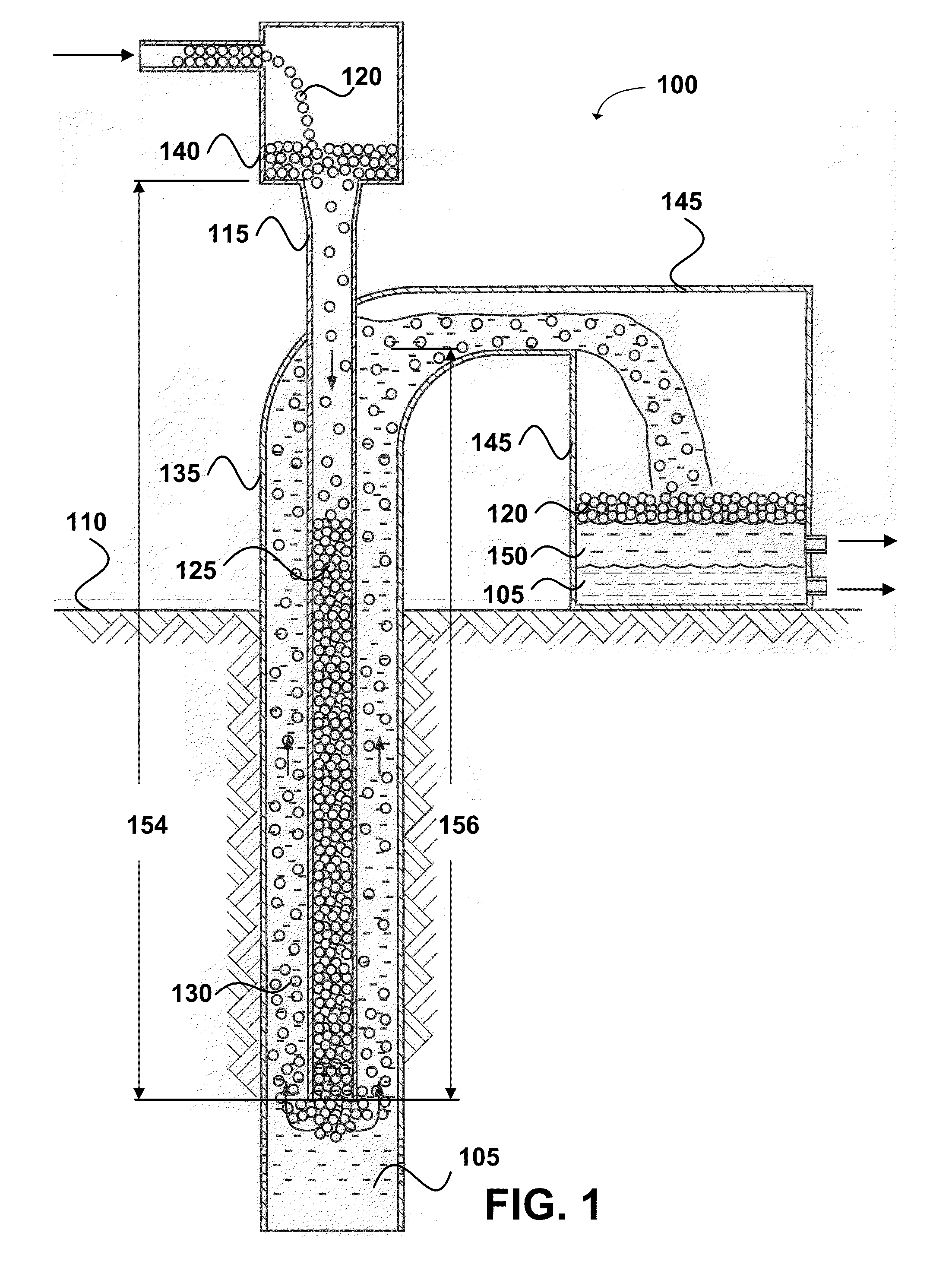
[0021]Present best known methods may include artificial lift via a high pressure source at the surface of a well to inject gas down an annulus and into a tubing bore. The compressed gas may be injected into the product stream through valves and may create an aeration or bubbling effect in the liquid column. The gas bubbles may expand as they rise to the surface, displacing liquid around them. This may decrease the den...


PUM


Abstract

A hydrocarbon lift system and method for increasing petroleum production from an enclosed subterranean reservoir to the earth's surface comprises a column of buoyant balls in an outer pipe configured to entrain the buoyant balls into a first fluid in an annulus formed with an inner pipe drill string. A pressure differential in the inner pipe with respect to the reservoir via the entrained buoyant balls in a second fluid therein lifts the second fluid and the entrained balls via the inner pipe to increase petroleum production to the earth's surface. A controlled rise velocity of the buoyant balls and the second fluid is predetermined by a ratio of a mass density of the buoyant balls to a mass density of the second fluid being greater than a mass density of the buoyant balls to a mass density of the first fluid for an increase over time in oil production.

Description

CROSS-REFERENCE TO RELATED APPLICATIONS[0001]This application is a continuation-in-part of and claims the benefit of the priority date of earlier filed U.S. Non-Provisional Utility application Ser. No. 13 / 706,150, filed Dec. 5, 2012 for Rod D. Smith, which claims the benefit of earlier filed U.S. Non-Provisional patent application Ser. No. 13 / 568,471, now U.S. Pat. No. 8,430,172 filed Aug. 7, 2012 for Rod D. Smith et al. which claims the benefit of earlier filed U.S. Provisional Patent Application Ser. No. 61 / 659,394, filed Jun. 13, 2012 for Rod D. Smith, each incorporated herein by reference in its entirety.BACKGROUND AND FIELD OF INVENTION[0002]By some measures, a total of about 707,000 barrels of oil per day were produced in the United States in 1998 using Enhanced Oil Recovery (EOR) methods, accounting for about 12% of total national crude oil production. Methods vary including thermal (steam and hot water), gas (carbon dioxide, nitrogen), chemical and even microbial enhanced oi...

Claims


Application Information

Patent Timeline
IPC IPC(8): E21B43/12
CPCE21B43/121
Inventor SMITH, RODNEY D.
Owner SMITHSONIAN ENERGY
Why Eureka
Try Eureka