Polarization-influencing optical arrangement, in particular in a microlithographic projection exposure apparatus

Active Publication Date: 2014-10-23
CARL ZEISS SMT GMBH
View PDF4 Cites 4 Cited by
  • Summary
  • Abstract
  • Description
  • Claims
  • Application Information

AI Technical Summary

Benefits of technology

[0039]The photoelastic modulators (PEM) are optical components which are produced from a material which exhibits stress birefringence in such a way that an excitation of the PEM to effect acoustic oscillations leads to a periodically changing mechanical stress and thus to a temporally varying retardation. Photoelastic modulators (PEM) of this type are known in the prior art e.g. from U.S. Pat. No. 5,886,810 A1 or U.S. Pat. No. 5,744,721 A1 and are produced and sold for use at wavelengths of visible light through to the VUV range (approximately 130 nm) e.g. by Hinds Instruments Inc., Hillsboro, Oreg. (USA). The crystal material of the PEM is caused to effect oscillations typically via an electrical voltage being applied to piezoelectric contacts fitted to the crystal material of the PEM, wherein the pulse frequency of the laser can be tuned to the frequency of the applied electrical voltage e.g. such that a laser pulse impinges on the PEM in each case at the maximum of the

Problems solved by technology

Depending on the concrete use situation, however, the problem can occur that the retardation provided by the polarization-influencing element of the arrangement is dependent on the propagation direction of the electromagnetic radiation in the (linearly or circularly) birefringent material and thus on the angle of incidence of the electromagnetic radiation on the polarization-influencing element or arrangement.
A further problem that occurs using polarization-influencing elements or arrangements in a microlithographic projection exposure apparatus is that the polarization-influencing effect of the element or arrangement is generally dependent on the polarization state of the electromagnetic radiation passing through the element or arrangement, wherein different illuminatio

Method used


Image

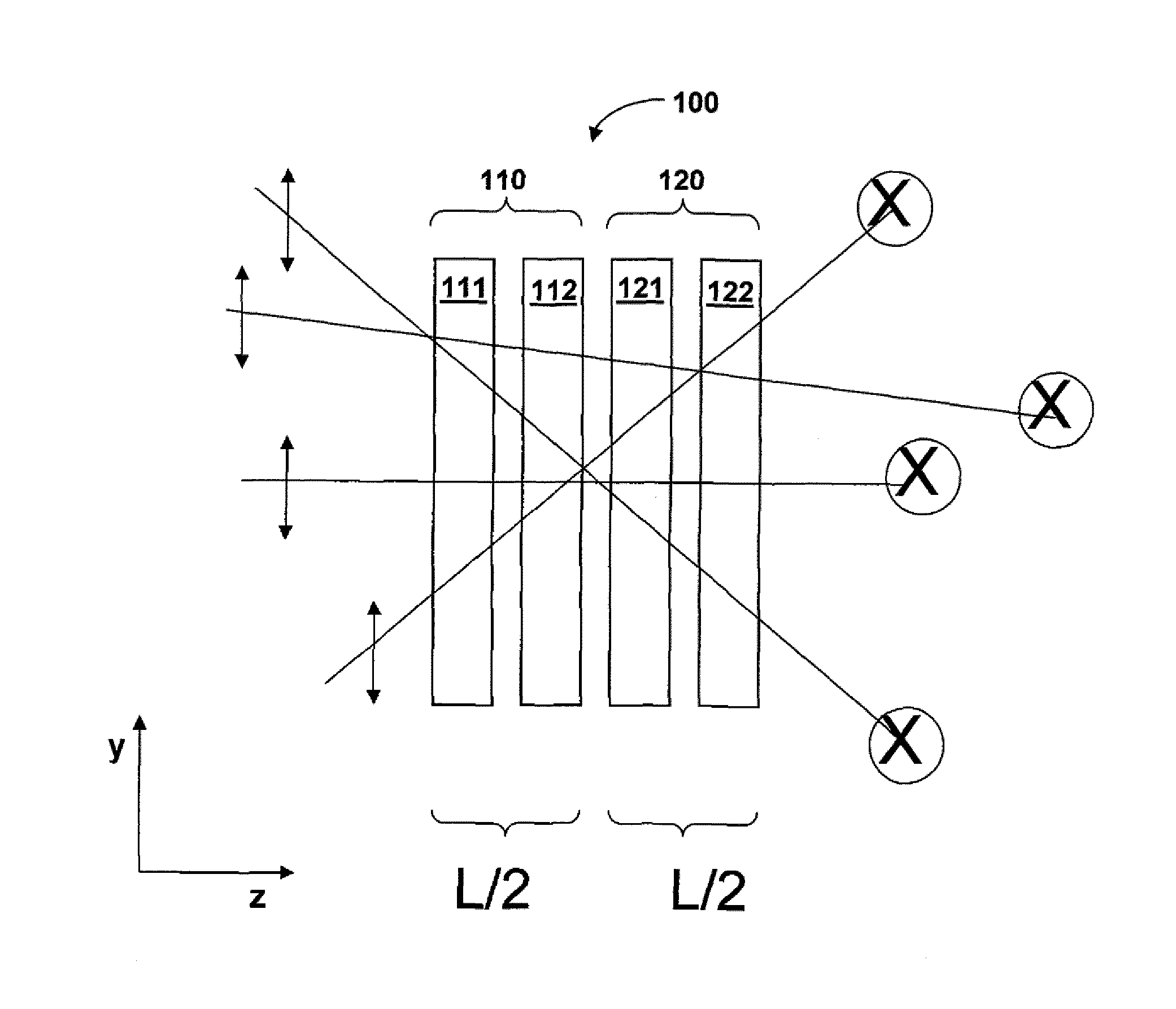
  • Polarization-influencing optical arrangement, in particular in a microlithographic projection exposure apparatus
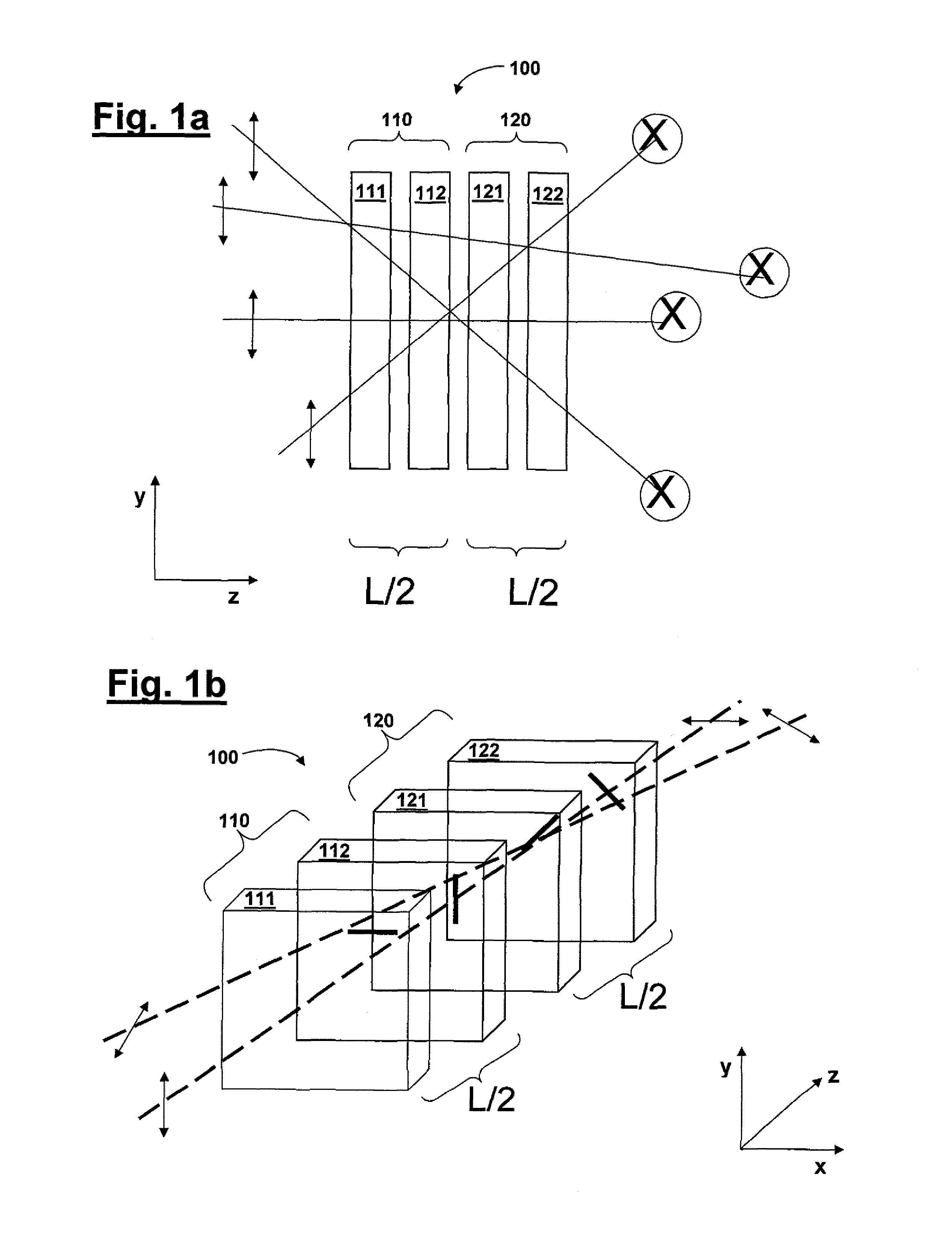
  • Polarization-influencing optical arrangement, in particular in a microlithographic projection exposure apparatus
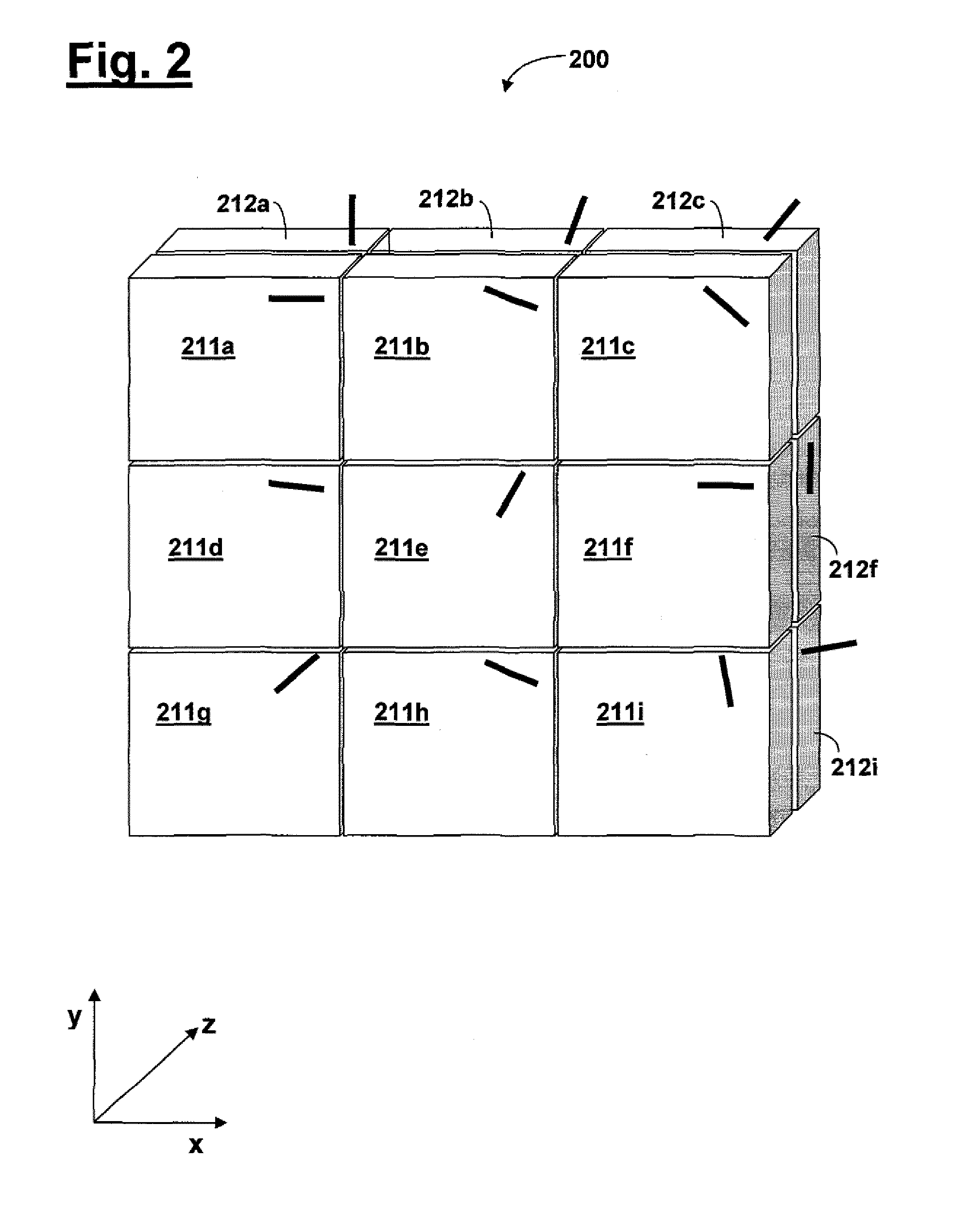
  • Polarization-influencing optical arrangement, in particular in a microlithographic projection exposure apparatus

Examples


Embodiment Construction

[0049]FIG. 5 shows in schematic illustration a microlithographic projection exposure apparatus 500 comprising a light source unit 501, an illumination device 510, a mask 525 comprising structures to be imaged, a projection lens 530 and a substrate 540 to be exposed. The light source unit 501 comprises as light source a DUV or VUV laser, for example an ArF laser for 193 nm, an F2 laser for 157 nm, an Ar2 laser for 126 nm or an Ne2 laser for 109 nm, and a ray shaping optical unit that generates a parallel light beam. The rays of the light beam have a linear polarization distribution, when the oscillation planes of the electric field vector of the individual light rays run in a uniform direction.

[0050]The parallel light beam impinges on a divergence-increasing optical element 511. By way of example, a diffractive optical element (DOE) can be used as the divergence-increasing optical element 511. This element is followed by a zoom lens 512, which generates a parallel light beam having a...


PUM


Abstract

A polarization-influencing optical arrangement comprises a first retardation element and a second retardation element.

Description

CROSS REFERENCE TO RELATED APPLICATIONS[0001]This application is a continuation of, and claims benefit under 35 USC 120 to, international application PCT / EP2013 / 050462, filed Jan. 11, 2013, which claims priority of German Patent Application 10 2012 200 368.1 filed on Jan. 12, 2012. The content of these applications is hereby incorporated by reference.BACKGROUND OF THE INVENTION[0002]1. Field of the Invention[0003]The invention relates to a polarization-influencing optical arrangement, in particular in a microlithographic projection exposure apparatus.[0004]2. Prior Art[0005]Microlithography is used for producing microstructured components, such as, for example, integrated circuits or LCDs. The microlithography process is carried out in a so-called projection exposure apparatus comprising an illumination device and a projection lens. The image of a mask (=reticle) illuminated via the illumination device is in this case projected, via the projection lens, onto a substrate (e.g. a sili...

Claims


Application Information

Patent Timeline
IPC IPC(8): G03F7/20G02B5/30
CPCG02B5/3083G03F7/7015G02B27/281G03F7/70275G03F7/70308G03F7/70566G03F7/70891G03F7/70966
Inventor SAENGER, INGOSCHLESENER, FRANK
Owner CARL ZEISS SMT GMBH
Why Eureka
Try Eureka