Enhancement of thermoelectric properties through polarization engineering

US20140318592A1Inactive Publication Date: 2014-10-30RGT UNIV OF CALIFORNIA

Image

  • Enhancement of thermoelectric properties through polarization engineering
  • Enhancement of thermoelectric properties through polarization engineering
  • Enhancement of thermoelectric properties through polarization engineering

Examples


Embodiment Construction

[0021]In the following description of the preferred embodiment, reference is made to the accompanying drawings which form a part hereof, and in which is shown by way of illustration a specific embodiment in which the invention may be practiced. It is to be understood that other embodiments may be utilized and structural changes may be made without departing from the scope of the present invention.

Technical Description

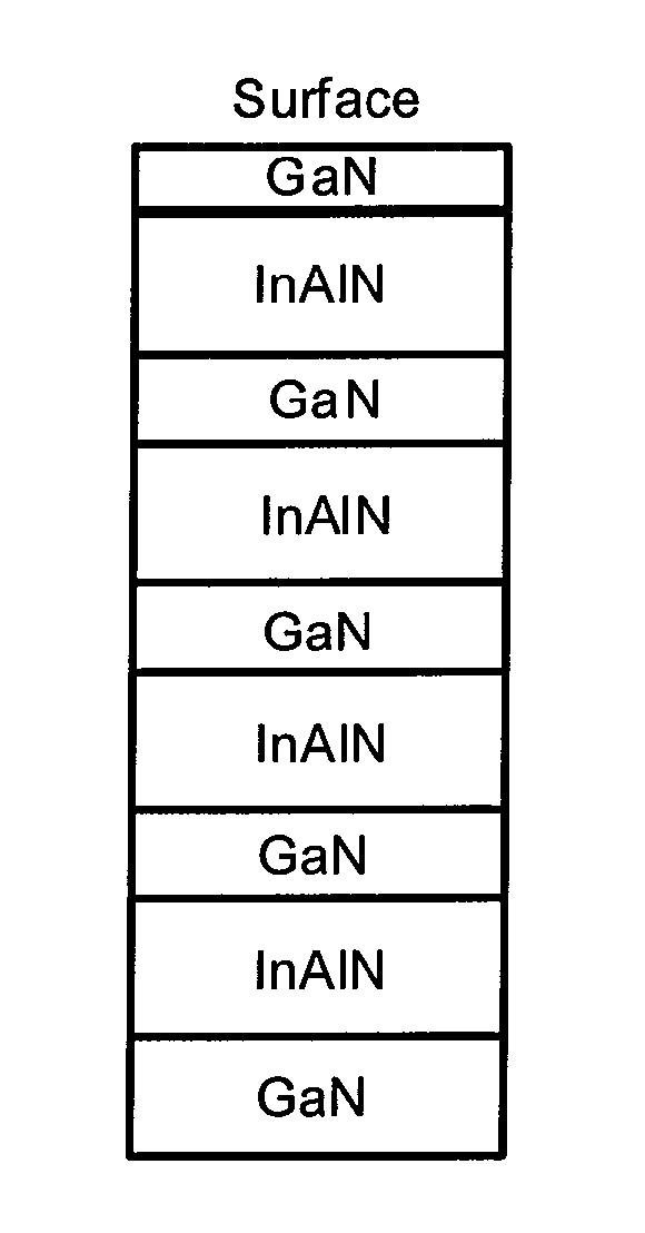
[0022]The present invention discloses a method of improving ZT beyond bulk values through the use of interfacial properties within a material. By intelligently designing the distribution of charge within a material, the electrical properties can be improved while simultaneously reducing thermal conductivity. This can allow for improved thermoelectric figure of merit, ZT.

[0023]In general, the thermal conductivity and electrical conductivity of a material move in the same direction as parameters are changed. This is because many features, such as dopant atoms or grain bou...


PUM

PropertyMeasurementUnit
Density of statesaaaaaaaaaa
Compositionaaaaaaaaaa
Concentrationaaaaaaaaaa

Abstract

A method for enhancement of thermoelectric properties through polarization engineering. Internal electric fields created within a material are used to spatially confine electrons for the purpose of enhancing thermoelectric properties. Electric fields can be induced within a material by the presence of bound charges at interfaces. A combination of spontaneous and piezoelectric polarization can induce this interfacial charge. The fields created by these bound charges have the effect of confining charge carriers near these interfaces. By confining charge carriers to a channel where scattering centers can be deliberately excluded the electron mobility can be enhanced, thus enhancing thermoelectric power factor. Simultaneously, phonons will not be affected by the fields and thus will be subject to the many scattering centers present in the majority of the structure. This allows for simultaneous enhancement of power factor and reduction of thermal conductivity, thus improving the thermoelectric figure of merit, ZT. This approach is also compatible with other strategies for reducing thermal conductivity, for example the inclusion of nanostructures.

Description

CROSS REFERENCE TO RELATED APPLICATIONS[0001]This application claims the benefit under 35 U.S.C. Section 119(e) of U.S. Provisional Application Ser. No. 61 / 578,808, filed on Dec. 21, 2011, by Alexander Sztein, John E. Bowers, Steven P. DenBaars, and Shuji Nakamura, and entitled “ENHANCEMENT OF THERMOELECTRIC PROPERTIES THROUGH POLARIZATION ENGINEERING,” attorneys' docket number 30794.443-US-P1 (2012-369-1), which application is hereby incorporated by reference herein.[0002]This application is related to the following co-pending and commonly-assigned application:[0003]U.S. Utility application Number Ser. No. 13 / 089,138, filed on Apr. 18, 2011, by Hiroaki Ohta, Alexander Sztein, Steven P. DenBaars, and Shuji Nakamura, and entitled “III-V NITRIDE-BASED THERMOELECTRIC DEVICE,” attorney's docket number 30794.304-US-U1 (2009-389-2), which application claims the benefit under 35 U.S.C. Section 119(e) of co-pending and commonly-assigned U.S. Provisional Application Ser. No. 61 / 325,177, file...

Claims


Application Information

Patent Timeline
30 Oct 2014
Publication
US20140318592A1
IPC
H01L35/22; C30B25/02; H01L35/34; C30B23/06
CPC
H01L35/22; H01L35/34; C30B25/02; C30B23/066; H10N10/857; H10N10/855; H10N10/01
Inventors
SZTEIN, ALEXANDER; BOWERS, JOHN E.