Coil arrangement for mpi

Active Publication Date: 2014-10-30
KONINKLJIJKE PHILIPS NV
View PDF7 Cites 15 Cited by
  • Summary
  • Abstract
  • Description
  • Claims
  • Application Information

AI Technical Summary

Benefits of technology

[0009]It is an object of the present invention to provide a coil arrangement which is more suitable for the examination of larger subjects (human beings, animals), in particular for adult human beings, by use of an MPI apparatus. Further, it is

Problems solved by technology

Further, the design of the MPI apparatus and methods

Method used


Image

  • Coil arrangement for mpi
  • Coil arrangement for mpi
  • Coil arrangement for mpi

Examples


embodiment 10

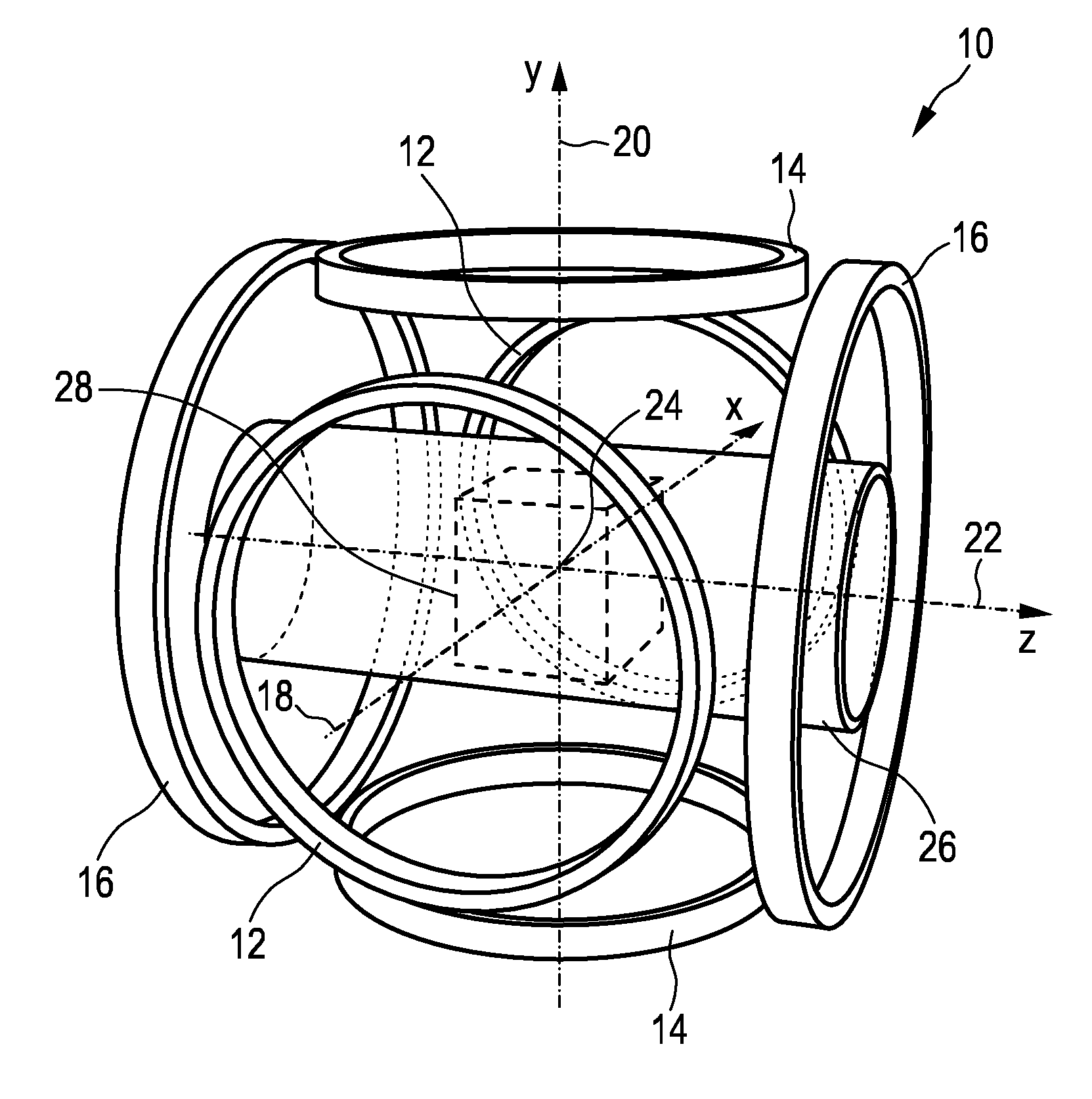
[0089]the MPI scanner has at least one further pair, preferably three further pairs, of parallel circular coils, again oriented along the x-, y-, and z-axes. These coil pairs, which are not shown in FIG. 1, serve as receive coils. As with the coil pairs 12, 14, 16 for the drive and focus fields, the magnetic field generated by a constant current flowing through one of these receive coil pairs is spatially nearly homogeneous within the field of view and parallel to the axis of the respective coil pair. The receive coils are supposed to be well decoupled. The time-dependent voltage induced in a receive coil is amplified and sampled by a receiver attached to this coil. More precisely, to cope with the enormous dynamic range of this signal, the receiver samples the difference between the received signal and a reference signal. The transfer function of the receiver is non-zero from zero Hertz (“DC”) up to the frequency where the expected signal level drops below the noise level. Alternat...

embodiment 30

[0101]The z-axis 42 of this embodiment 30 is oriented vertically, while the x- and y-axes 38, 40 are oriented horizontally. The bore 46 of the scanner is parallel to the x-axis 38 and, thus, perpendicular to the axis 42 of the selection field. The drive field is generated by a solenoid (not shown) along the x-axis 38 and by pairs of saddle coils (not shown) along the two remaining axes 40, 42. These coils are wound around a tube which forms the bore. The drive field coils also serve as receive coils.

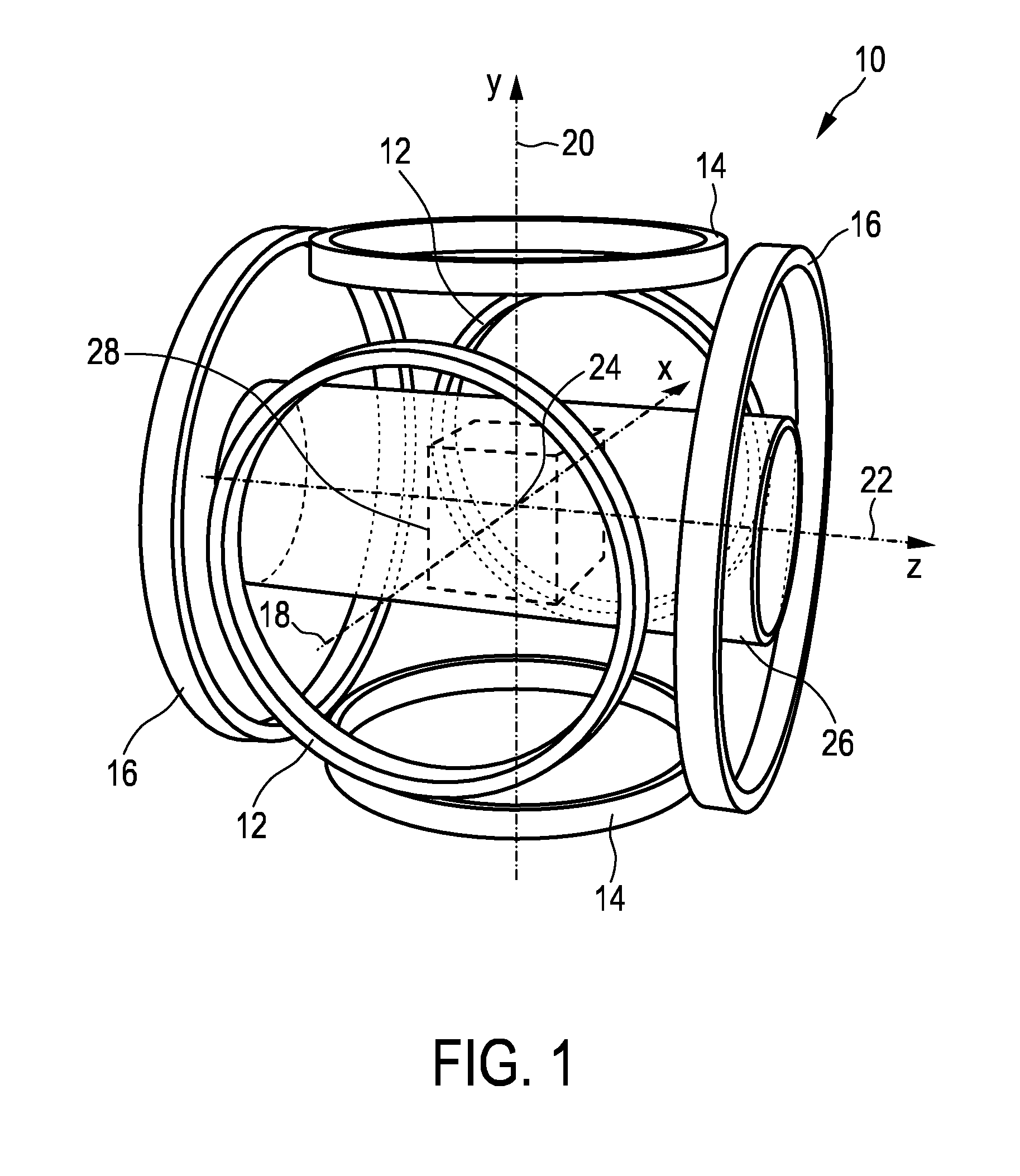
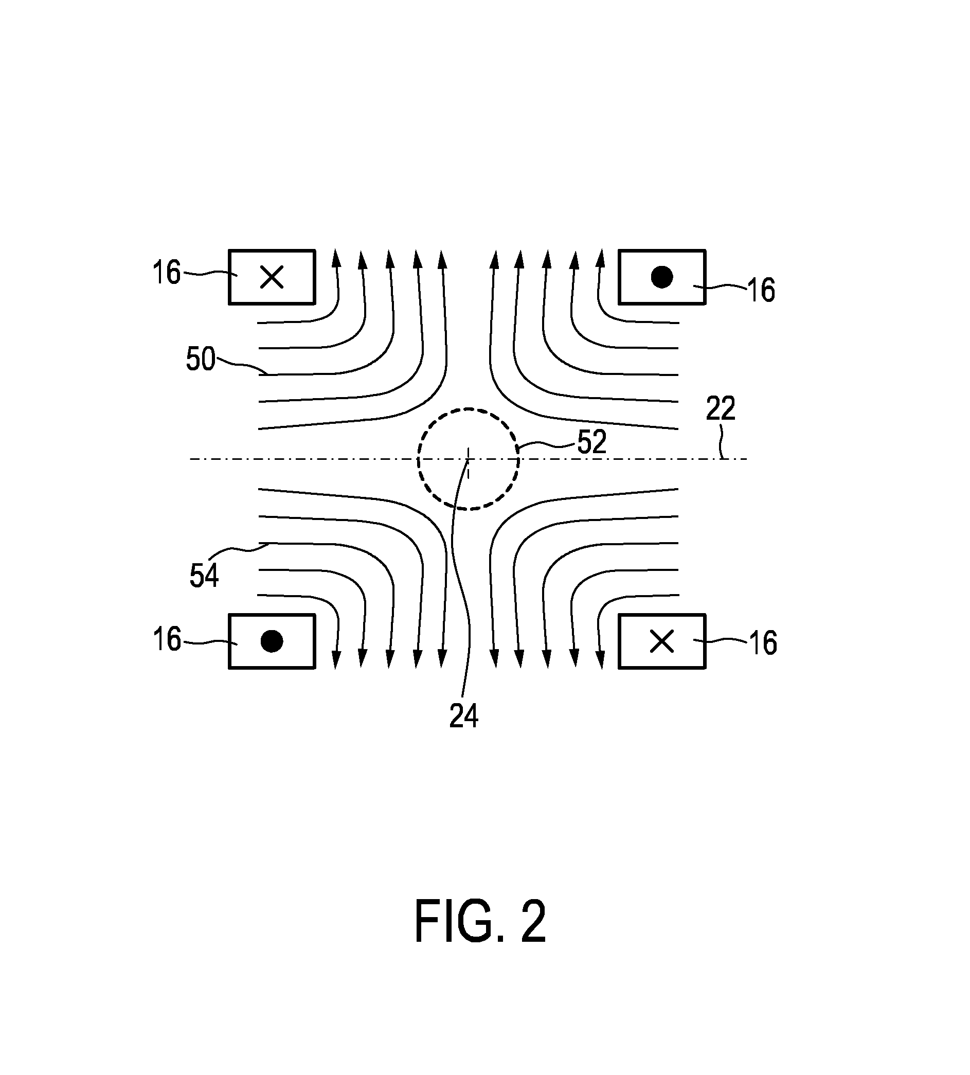
[0102]To give a few typical parameters of such an embodiment: The z-gradient of the selection field, G, has a strength of G / μ0=2.5 T / m, where μ0 is the vacuum permeability. The temporal frequency spectrum of the drive field is concentrated in a narrow band around 25 kHz (up to approximately 150 kHz). The useful frequency spectrum of the received signals lies between 50 kHz and 1 MHz (eventually up to approximately 15 MHz). The bore has a diameter of 120 mm. The biggest cube 28 that fits ...


PUM


Abstract

The present invention relates to a coil arrangement, in particular for use in a magnetic particle imaging apparatus (100), comprising a coil split into at least two coil segments, wherein the winding direction is inverted between at least one coil segment to another coil segment, and a capacitor coupled between at least two adjacent coil segments. Further, the present invention relates to such a magnetic particle imaging apparatus, in particular an apparatus (100) for influencing and/or detecting magnetic particles in a field of view (28), which apparatus comprises selection means and drive means (120) wherein at least one drive field coil and/or at least one selection field coil representing a selection field element is implemented by a coil arrangement as proposed according to the present invention.

Description

FIELD OF THE INVENTION[0001]The present invention relates to a coil arrangement, in particular for use in a magnetic particle imaging apparatus. Further, the present invention relates to such a magnetic particle imaging apparatus, in particular an apparatus for influencing and / or detecting magnetic particles in a field of view.BACKGROUND OF THE INVENTION[0002]Magnetic Particle Imaging (MPI) is an emerging medical imaging modality. The first versions of MPI were two-dimensional in that they produced two-dimensional images. Newer versions are three-dimensional (3D). A four-dimensional image of a non-static object can be created by combining a temporal sequence of 3D images to a movie, provided the object does not significantly change during the data acquisition for a single 3D image.[0003]MPI is a reconstructive imaging method, like Computed Tomography (CT) or Magnetic Resonance Imaging (MRI). Accordingly, an MP image of an object's volume of interest is generated in two steps. The fi...

Claims


Application Information

Patent Timeline
IPC IPC(8): G01R33/385
CPCG01R33/385A61B5/0515H01F7/20
Inventor SCHMALE, INGO
Owner KONINKLJIJKE PHILIPS NV
Why Eureka
Try Eureka