Method of determining the configuration of an ophthalmic filter

a technology of ophthalmic filter and configuration, applied in the field of optical devices, can solve problems such as retinal damage or contribution, and achieve the effects of reducing the distortion of colour vision, limiting the perturbation of scotopic vision, and increasing the rejection ra

Active Publication Date: 2014-10-30
ESSILOR INT CIE GEN DOPTIQUE +1
View PDF7 Cites 28 Cited by
  • Summary
  • Abstract
  • Description
  • Claims
  • Application Information

AI Technical Summary

Benefits of technology

[0031]Moreover, the selective interferential filtering means may be configured, as a dual band filter for selectively inhibiting light in a narrow band of wavelengths centered on a wavelength around 435 nm which has been shown by the cellular model studies to be harmful to the progress of AMD, Stargardt disease, retinitis pigmentosa or Best's disease; and in a narrow band of wavelengths centered on a wavelength around 460 nm which has been shown by the cellular model studies to be harmful to the progress of Glaucoma, Leber's hereditary optic neuropathy or diabetic retinopathy. This embodiment provides increased selectivity thereby limiting the distortion of colour vision and the perturbation of scotopic vision.
[0032]In another embodiment, the first selected range of wavelengths has a bandwidth in a range of from 15 nm to 30 nm, preferably 15 nm to 25 nm centered on a wavelength of substantially 435 nm, 445 nm or 460 nm, and the first rate of rejection is in a range of from 60 to 100%, preferably of from 80 to 100%. The increased rate of rejection provides enhance protection, in particular for those suffering from a disease such as AMD, Stargardt disease, retinitis pigmentosa, Best's disease, glaucoma, Leber's hereditary optic neuropathy or diabetic retinopathy, helping to slow down the progress of the disease.

Problems solved by technology

Visible light, even of ordinary everyday intensity, may cause retinal damage or contribute to the development of early and late Age-Related Maculopathy (ARM), such as Age-related Macular Degeneration (AMD).

Method used


Image

  • Method of determining the configuration of an ophthalmic filter
  • Method of determining the configuration of an ophthalmic filter
  • Method of determining the configuration of an ophthalmic filter

Examples


first embodiment

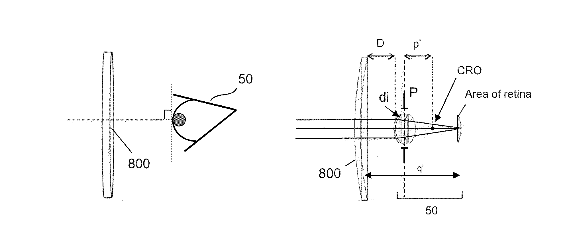
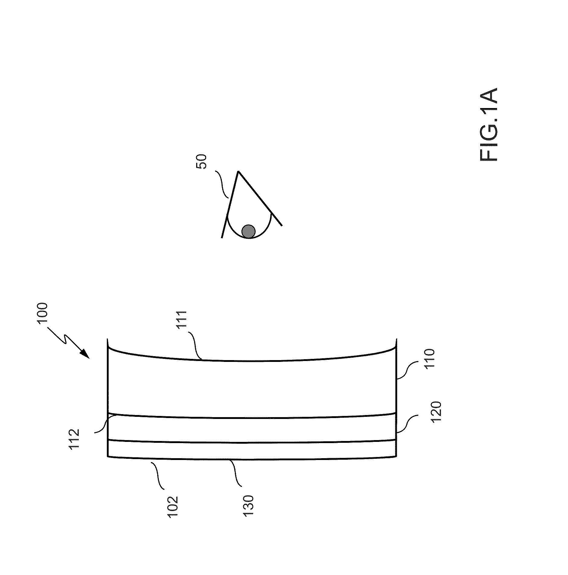
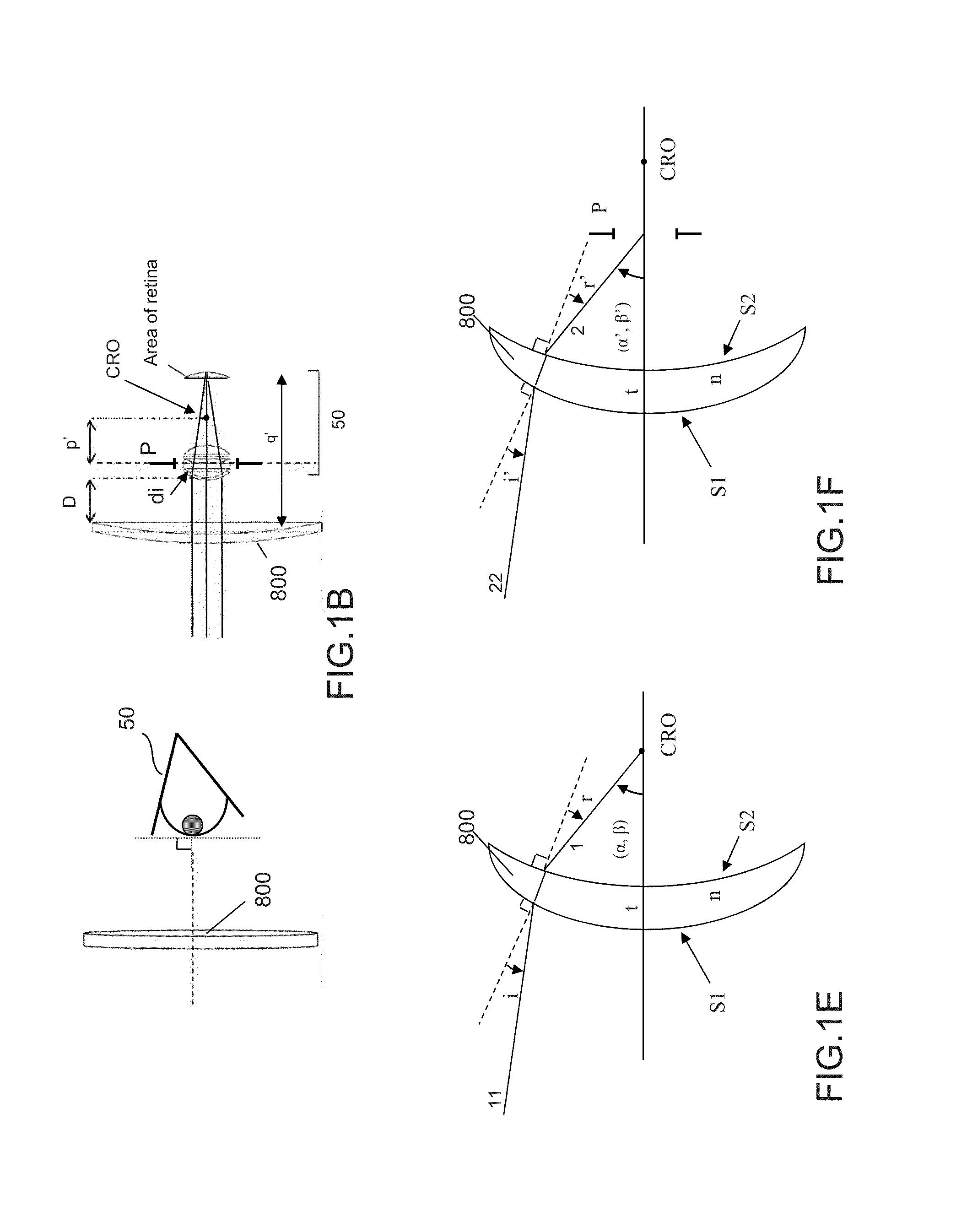
[0064]An optical device according to the invention will be described with reference to FIG. 1A. FIG. 1A is a schematic diagram of an optical lens 100 comprising a base optical substrate 110 having a first surface 111 and a second surface 112. In the specific embodiment of an optical lens the first surface 111 is a concave back surface, disposed, in use, proximal to an eye 50 of a user and the second surface 112 is a convex front surface disposed, in use, distal to the eye 50 of the user. The optical lens 100 further comprises a selective interferential filter 120 provided, in this particular embodiment, as a layer, on the front surface 112 of the base optical substrate 110 and shaped to conform with the shape of the front surface 112. In other embodiments the selective interferential filter may be provided, as a layer, or as part of a layer, within the optical substrate 110.

[0065]The selective interferential filter 120 operates as a band stop filter selectively inhibiting transmissi...

second embodiment

[0127]The back surface 311 of the optical substrate may be provided with a layer of absorption material 324, similar to the layer of absorptive material of the second embodiment, configured to absorb light in the target bandwidth of the selective interferential filter 322 and / or the selective interferential filter 320. The provision of absorption material 324 in this way significantly reduces the parasitic light that reaches the user's eye, coming from light incident on the back surface 311 of the optical device and reflected by the selective interferential filter 322 and / or the selective interferential filter 320. Moreover, the absorption material 324 enhances the spectral filtering introduced by the selective interferential filter 322 and / or the selective interferential filter 320.

[0128]Like the layer of absorptive material of the previous embodiment, the absorptive layer 324 may also be configured to absorb light in a wavelength band different to the target bandwidth of the selec...

fourth embodiment

[0130]An optical device according to the invention will be described with reference to FIG. 4. FIG. 4 is a schematic diagram of an optical lens 400 comprising a base optical substrate 410 having a first surface 411 and a second surface 412. In the specific embodiment of an optical lens the first surface 411 is a concave back / posterior surface, disposed proximal to an eye 50 of a user in use and the second surface 412 is a convex front / anterior surface disposed in use distal to the eye 50 of the user. The optical lens further comprises an absorptive filter 420 provided, in this embodiment, within the volume of the base optical substrate 410. The absorptive filter 420 in this embodiment is provided as a film containing a dye or pigment and interposed between two layers of the base optical substrate 410. In other embodiments of the invention the absorptive layer may be provided on either surface of the optical substrate.

[0131]The absorptive filter 420 operates as a band stop filter sel...


PUM


Abstract

Method of determining configuration of interferential filtering elements for an optical device having an optical substrate for a user, includes:
    • providing a first set of parameters representative of at least one main line of sight of the user;
    • determining a first selected range of angles of incidence based on the first parameters;
    • providing a second set of parameters characterizing, for the user, a range of wavelengths to be at least partially inhibited;
    • determining a first selected range of wavelengths of incident light to be at least partially inhibited, based on the second parameters; and
    • configuring a first selective interferential filtering element and a first zone of a surface of the optical substrate based on the first selected range of angles of incidence and wavelengths such that the first selective interferential filtering elements inhibit, at a first rate of rejection, transmission of the first selected range of wavelengths of incident light.

Description

FIELD OF THE INVENTION[0001]The present invention relates in general to an optical device comprising an optical substrate and to the use of such an optical device. Embodiments of the invention relate to a method of determining a configuration for an optical device, a method of manufacturing an optical device and use of an optical device.BACKGROUND OF THE INVENTION[0002]The electromagnetic spectrum covers a wide range of wavelengths, among which are wavelengths visible to the human eye often referred to as the visible spectrum covering a range of from 380 nm to 780 nm. Some wavelengths of the electromagnetic spectrum including those of the visible spectrum provide harmful effects, while others are known to have beneficial effects on the eye. Some wavelengths of the visible spectrum are also known to induce a range of neuroendocrine, physiological and behavioural responses known as non-image-forming (NIF) responses.[0003]The vertebrate retina is a light-sensitive tissue lining the inn...

Claims


Application Information

Patent Timeline
Patent Type & Authority Applications(United States)
IPC IPC(8): G02C13/00
CPCG02C13/005G02C7/104G02C7/105G02C7/107G02C7/108
Inventor COHEN-TANNOUDJI, DENISBARRAU, CORALIEVILLETTE, THIERRY PIERRESAHEL, JOSE-ALAINPICAUD, SERGEARNAULT, EMILIE
Owner ESSILOR INT CIE GEN DOPTIQUE
Why Eureka
Try Eureka