
Systems and Methods for Improving Image Quality in Cone Beam Computed Tomography

Inactive Publication Date: 2014-10-30
BOURLAND JOHN DANIEL +1
View PDF1 Cites 9 Cited by
  • Summary
  • Abstract
  • Description
  • Claims
  • Application Information

AI Technical Summary

Benefits of technology

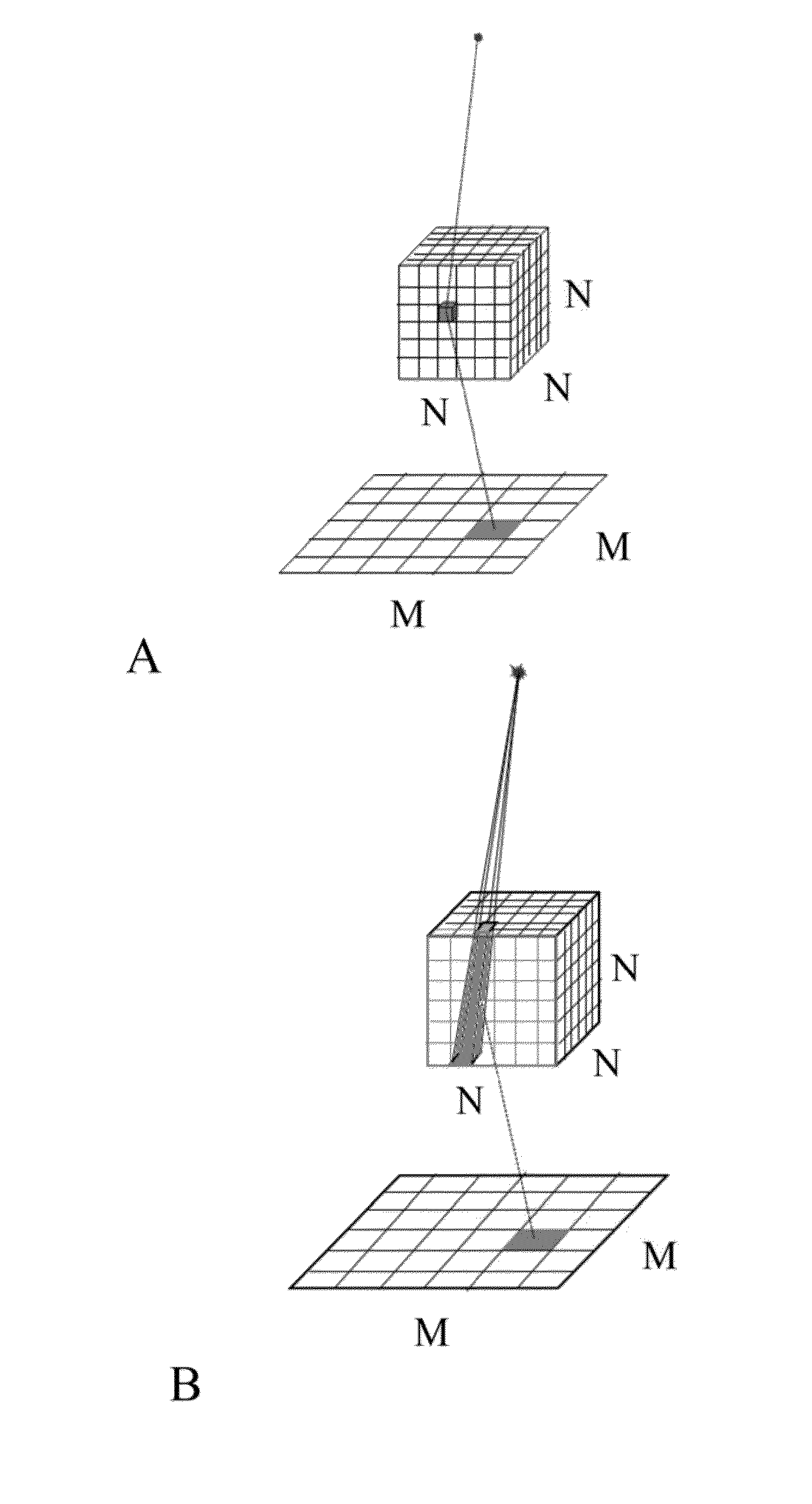
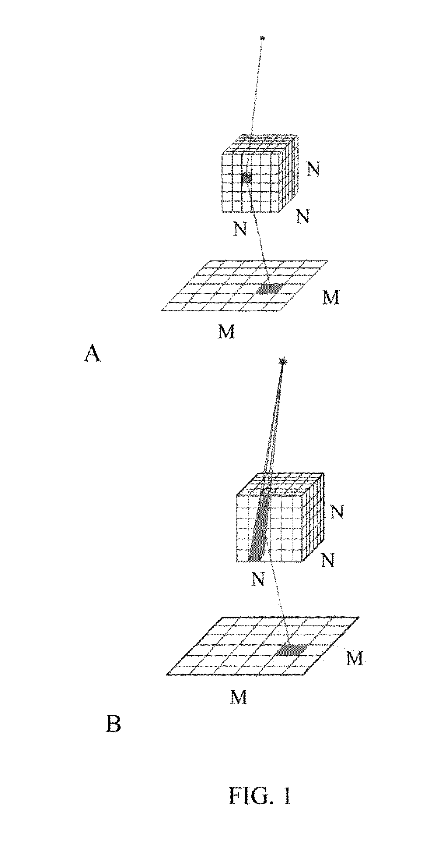
The present invention reduces the number of calculations needed by using "pencil beams" that treat each target as an integrated scattering target. This approach reduces the number of calculations from N3×M2 to N2×M2, making the process more efficient.

Problems solved by technology

These scattered photons degrade CT and CBCT image quality by contributing a background fluence to image pixels that decreases the signal-to-noise-ratio (SNR).
Thus, when performing a calculation using the KN model, the calculation expense for using the point model is N3×M2 calculations (wherein M is a dimension in two dimensional space of the three dimensional object projected / reduced into two dimensions).
The widely used Grangeat algorithm, familiar to those skilled in CBCT image processing, is limited to circular scanning trajectory and spherical objects.
However, there are some drawbacks that result from data collection methodologies.
One drawback is that high-level scattered x-ray radiation generated by the irradiated volume is also received by the planar x-ray image receptor that significantly impairs image quality by creating image reconstruction artifacts and substantially increasing noise.
Currently available methodologies to address these image quality problems tend to be expensive and time consuming (in computational time due to the very large 3D data sets).

Method used


Image

  • Systems and Methods for Improving Image Quality in Cone Beam Computed Tomography
  • Systems and Methods for Improving Image Quality in Cone Beam Computed Tomography
  • Systems and Methods for Improving Image Quality in Cone Beam Computed Tomography

Examples


Embodiment Construction

[0023]In one embodiment, the present invention relates to methods and associated instruments / computers using cone beam CT imaging, to do efficient (e.g., fast and accurate) calculations using various new algorithms to produce images that are of good or excellent quality.

[0024]In cone-beam computed tomography (CBCT), high-level scattered radiation originating in the irradiated volume significantly impairs image quality by creating image reconstruction artifacts and substantially increasing noise. Thus, in one embodiment of the present invention, scatter correction is performed in CBCT image reconstruction. Thus, the present invention should have clinical relevance to diagnostic imaging and image-guided radiation treatment. In one variation, the present invention relates to correcting the main components of scatter correction using algorithms that consist of an estimation model and a compensation approach.

[0025]In an embodiment, the present invention relates to an imaging system and a...


PUM


Abstract

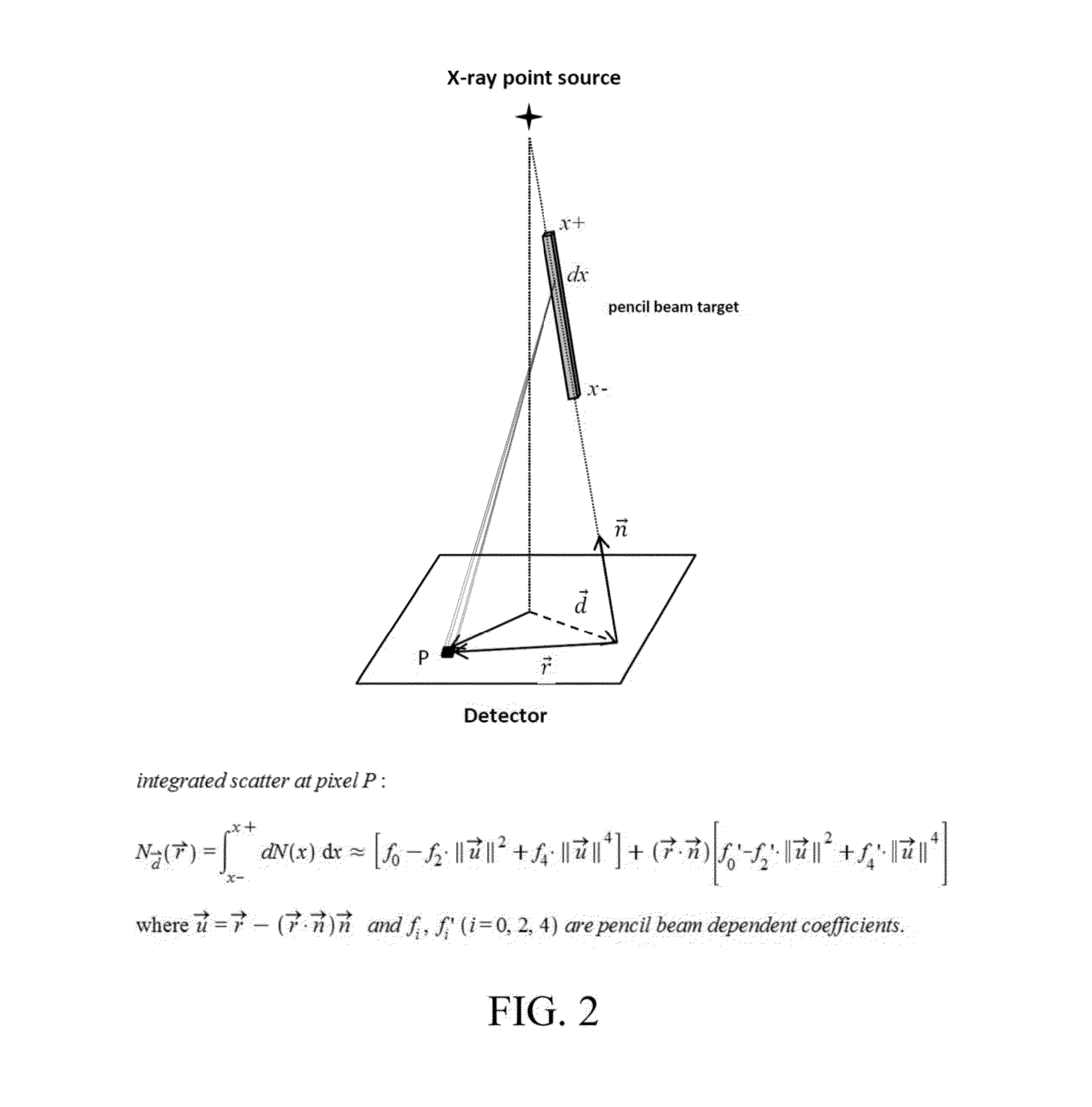
The present invention focuses on an analytical model for hist and accurate scatter estimation. The present invention uses the Klein-Nishina (KN) formula as a starting point, which gives the Compton scattering differential cross-section for an interaction point. For a direct integration of the point scatter kernel over the irradiated volume, the large number of KN formulae. (e.g., amount of solid angle subtended) and rays traced required for calculating attenuation makes the computation very expensive. The present invention reduces the 3D formulation into an efficient 2D approach by integrating the KN formula along an interaction line of tissue-equivalent medium. An average attenuation length was assumed for each interaction point on the beam to reduce the number of rays traced. In the case of kilovoltage (kV) x rays as the imaging source and a small imaging field, with in-field scatter, the line integral derived, can be approximated by a compact analytical form.

Description

[0001]This application claims priority under 35 USC 119 (e) to U.S. Provisional Application No. 61 / 816,504 filed Apr. 26, 2013, the entire contents of which are incorporated by reference in its entirety.FIELD OF THE INVENTION[0002]The present invention relates to computed tomography (CT) imaging systems and methods, in an embodiment, the invention relates to CT imaging systems and methods for probing internal structures of an object using x-ray ionizing radiation. In a variation, the present invention relates to x-ray ionizing radiation image recording methods and apparatuses for use in a cone-beam computed tomography (CBCT) systems.BACKGROUND OF THE INVENTION[0003]Scattered photons are produced in a subject being x-ray imaged either from x-ray Compton interactions (which is the dominant form) and x-ray Rayleigh interactions (the less dominant form). These scattered photons degrade CT and CBCT image quality by contributing a background fluence to image pixels that decreases the sign...

Claims


Application Information

Patent Timeline
IPC IPC(8): A61B6/00G01N23/04
CPCG01N23/046A61B6/5282A61B6/032A61B6/4085A61B6/5205A61B6/583G01N2223/401G06T11/006G06T2211/428
Inventor BOURLAND, JOHN DANIELLIU, JIE
Owner BOURLAND JOHN DANIEL
Learn More