Scanning probe, scanning observation system, integrated endoscope, and integrated endoscope system

a scanning observation and endoscope technology, applied in the field of scanning observation systems, can solve the problems of large heat radiation to the outside of the housing and keep the temperature in the housing constant, and achieve the effect of reducing the deformation of the scanned imag

Inactive Publication Date: 2014-10-30
HOYA CORP
View PDF6 Cites 19 Cited by
  • Summary
  • Abstract
  • Description
  • Claims
  • Application Information

AI Technical Summary

Benefits of technology

[0014]According to the invention, a scanning probe, a scanning observation system, an integrated endoscope and an integrated endoscope system suitable for reducing deformation of a scanned image which depends on the temperature change by keeping the temperature in the housing constant.

Problems solved by technology

Therefore, when the heater provided on an inner wall surface of the housing is heated, a large amount of heat is radiated to the outside of the housing.
Therefore, it is difficult in the configuration described in patent document 1 to keep the temperature in the housing constant.

Method used


Image

  • Scanning probe, scanning observation system, integrated endoscope, and integrated endoscope system
  • Scanning probe, scanning observation system, integrated endoscope, and integrated endoscope system
  • Scanning probe, scanning observation system, integrated endoscope, and integrated endoscope system

Examples


Embodiment Construction

[0019]In the following, an endoscope system according to an embodiment of the present invention is explained with reference to the accompanying drawings.

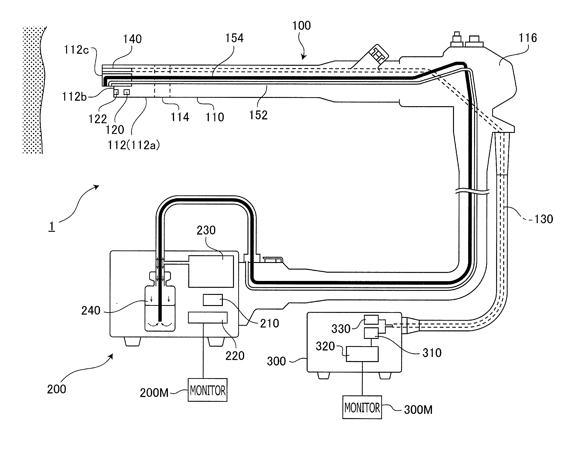
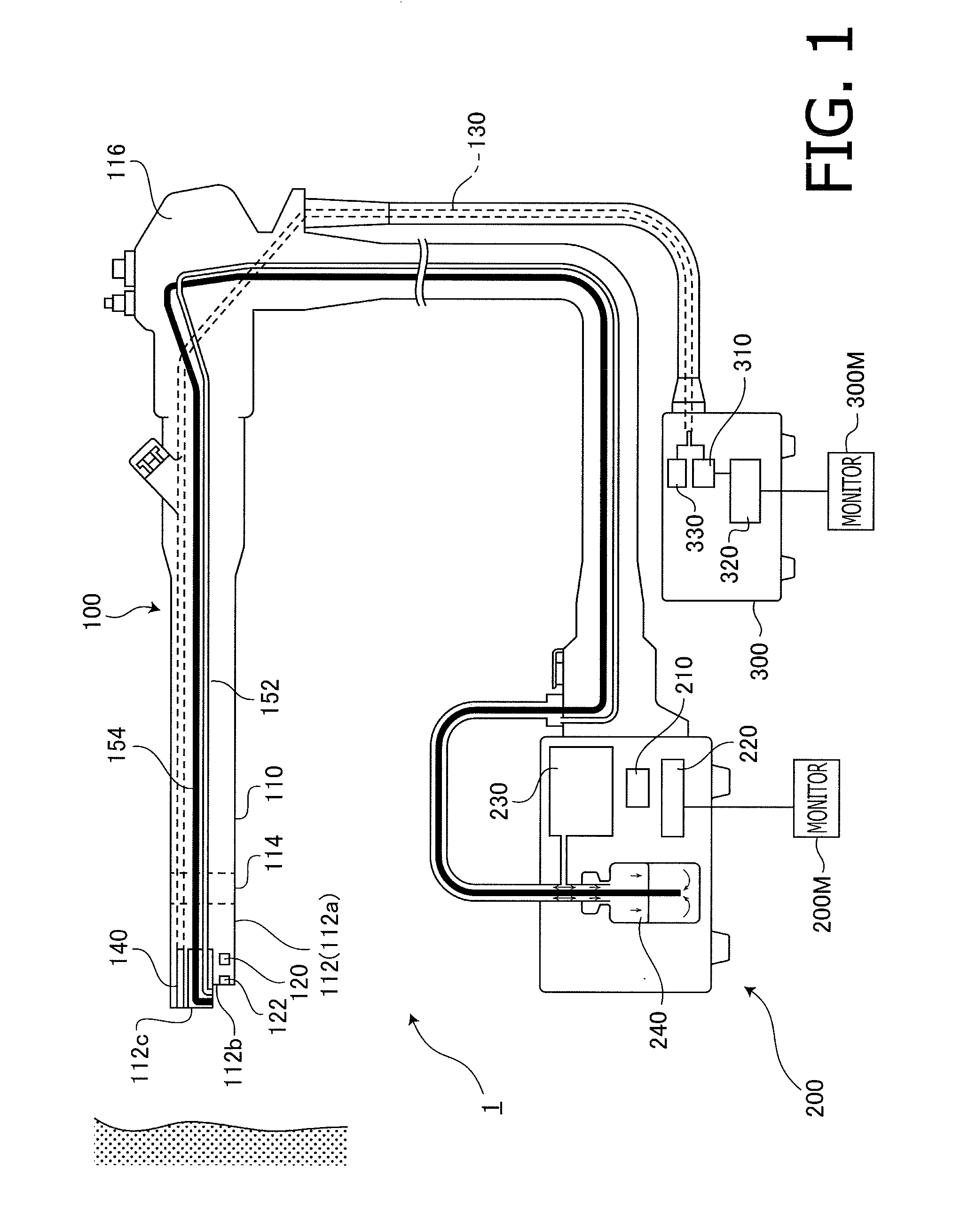
[0020]FIG. 1 is a block diagram illustrating a configuration of an endoscope system 1 according to the embodiment. As shown in FIG. 1, the endoscope system 1 has an integrated endoscope 100 for imaging a subject. The integrated endoscope 100 includes an insertion unit elastic tube 110 which is covered with an elastic sheath. To a tip of the insertion unit elastic tube 110, a proximal end of a tip part 112 covered with a resin housing (hereafter referred to as a “tip exterior housing 112a”) having rigidity is connected. A bending part 114 located at a joint part of the insertion unit elastic tube 110 and the tip part 112 is configured to be able to bend freely through a remote operation from a near-side operation unit 116 connected to a proximal end of the insertion unit elastic tube 110. This bending mechanism is a known mechanism i...


PUM


Abstract

An optical fiber that transmits scanning light to a subject; a housing holding the optical fiber; a vibration element fixed to an exit end part of the fiber and vibrating periodically the exit end part so that the scanning light emitted from the exit end part scans on the subject in a predetermined trajectory; a hollow tube formed so an inner circumferential surface of the hollow tube positioned outside a moving range of the exit end part and the vibration element surrounds an entire circumference of the exit end part and a movable part of the vibration element; a thermal detection sensor detecting temperature in a hollow space of the hollow tube; and a heating element laid on one of the inner and outer circumferential surface of the hollow tube and increases the temperature in the hollow space in response to the temperature detected by the thermal detection sensor.

Description

TECHNICAL FIELD[0001]The present invention relates to a scanning probe which scans on a subject with scanning light emitted from a light source, a scanning observation system including the scanning probe, an integrated endoscope integrally provided with the scanning probe and an electronic endoscope. and an integrated endoscope system including the integrated endoscope.BACKGROUND ART[0002]A scanning observation system which images a subject, such as a living tissue, with a scanning probe is known. The scanning probe of this type scans on a subject by emitting scanning light from an exit end of an optical fiber while vibrating the optical fiber using, for example, a piezoelectric actuator. A concrete configuration of a scanning probe is described, for example, in a domestic re-publication of PCT international application No. 2010-503890A (hereafter, referred to as “patent document 1”; see, for example, FIG. 8).[0003]The scanning probe described in patent document 1 has a cylindrical ...

Claims


Application Information

Patent Timeline
Patent Type & Authority Applications(United States)
IPC IPC(8): A61B1/00A61B5/00A61B1/12
CPCA61B1/00172A61B1/00165A61B5/0084A61B5/0062A61B1/128A61B5/0068G02B21/0036G02B21/0076G02B23/2407G02B23/243G02B23/2476G02B23/26G02B26/103
Inventor TORIUMI, SHUNSUKEKOBAYASHI, SHOTARO
Owner HOYA CORP
Why Eureka
Try Eureka