Direct solar steam generation

a technology of solar energy and steam generation, applied in the direction of steam generation using solar heat, cleaning using liquids, lighting and heating apparatus, etc., to achieve the effect of improving performance, efficiency, and utility of use, and facilitating the more rapid understanding

Active Publication Date: 2014-11-06
GLASSPOINT SOLAR
View PDF4 Cites 15 Cited by
  • Summary
  • Abstract
  • Description
  • Claims
  • Application Information

AI Technical Summary

Benefits of technology

[0020]The invention may be implemented in numerous ways, including as a process, an article of manufacture, an apparatus, a system, and a composition of matter. In this specification, these implementations, or any other form that the invention may take, may be referred to as techniques. The Detailed Description provides an exposition of one or more embodiments of the invention that enable improvements in performance, efficiency, and utility of use in the field identified above. The Detailed Description includes an Introduction to facilitate the more rapid understanding of the remainder of the Detailed Description. The Introduction includes Example Embodiments of one or more of systems, methods, articles of manufacture, and computer readable media in accordance with the concepts described herein. As is discussed in more detail in the Conclusions, the invention encompasses all possible modifications and variations within the scope of the issued claims.

Problems solved by technology

Due to a high volume of water needing treatment, in some scenarios, oilfield operations provide feed water to some steam generators that would not meet purity standards for high-pressure, high-temperature steam generation in other steam generators or boilers.
For another example, some of the techniques improve operation given that timing and amount of incoming solar radiation (sunshine) are not controllable.

Method used


Image

  • Direct solar steam generation
  • Direct solar steam generation
  • Direct solar steam generation

Examples


example embodiments

[0039]In concluding the introduction to the detailed description, what follows is a collection of example embodiments, including at least some explicitly enumerated as “ECs” (Example Combinations), providing additional description of a variety of embodiment types in accordance with the concepts described herein; these examples are not meant to be mutually exclusive, exhaustive, or restrictive; and the invention is not limited to these example embodiments but rather encompasses all possible modifications and variations within the scope of the issued claims.

[0040]ECI) A method comprising:[0041]transforming a section of pipe by shaping, coating, and mounting in place to form a plurality of continuous solar energy receiver pipes.

[0042]EC2) The method of ECI, wherein the section of pipe is a single section of pipe.

[0043]EC3) The method of ECI, further comprising operating at least a portion of the continuous solar energy receiver pipes in parallel and balancing liquid flow across the con...

selected embodiment details

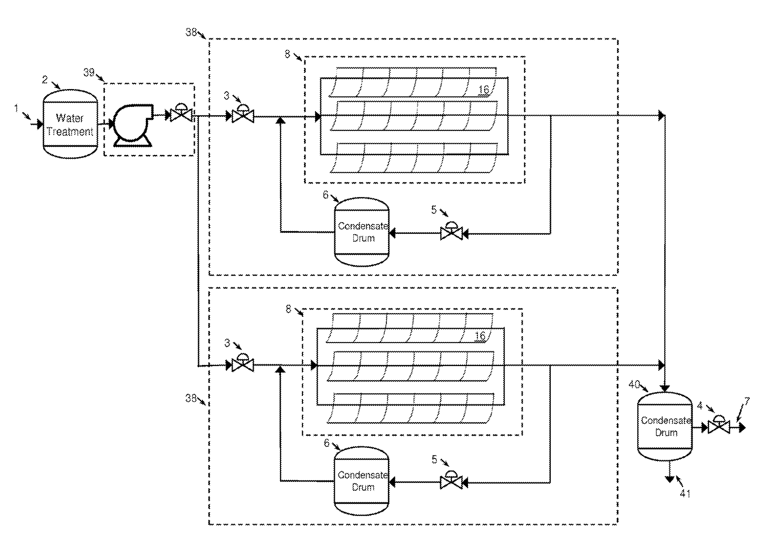
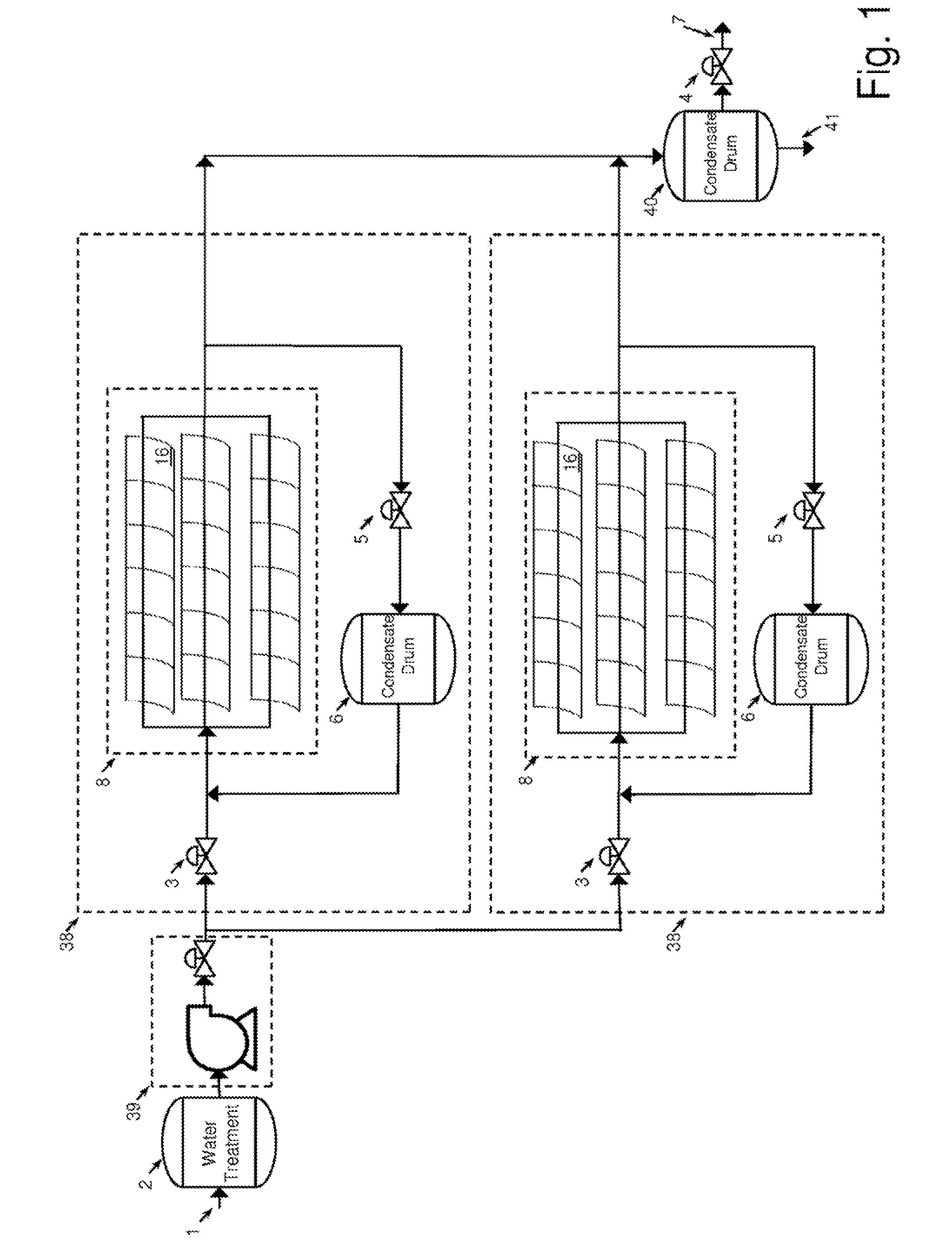
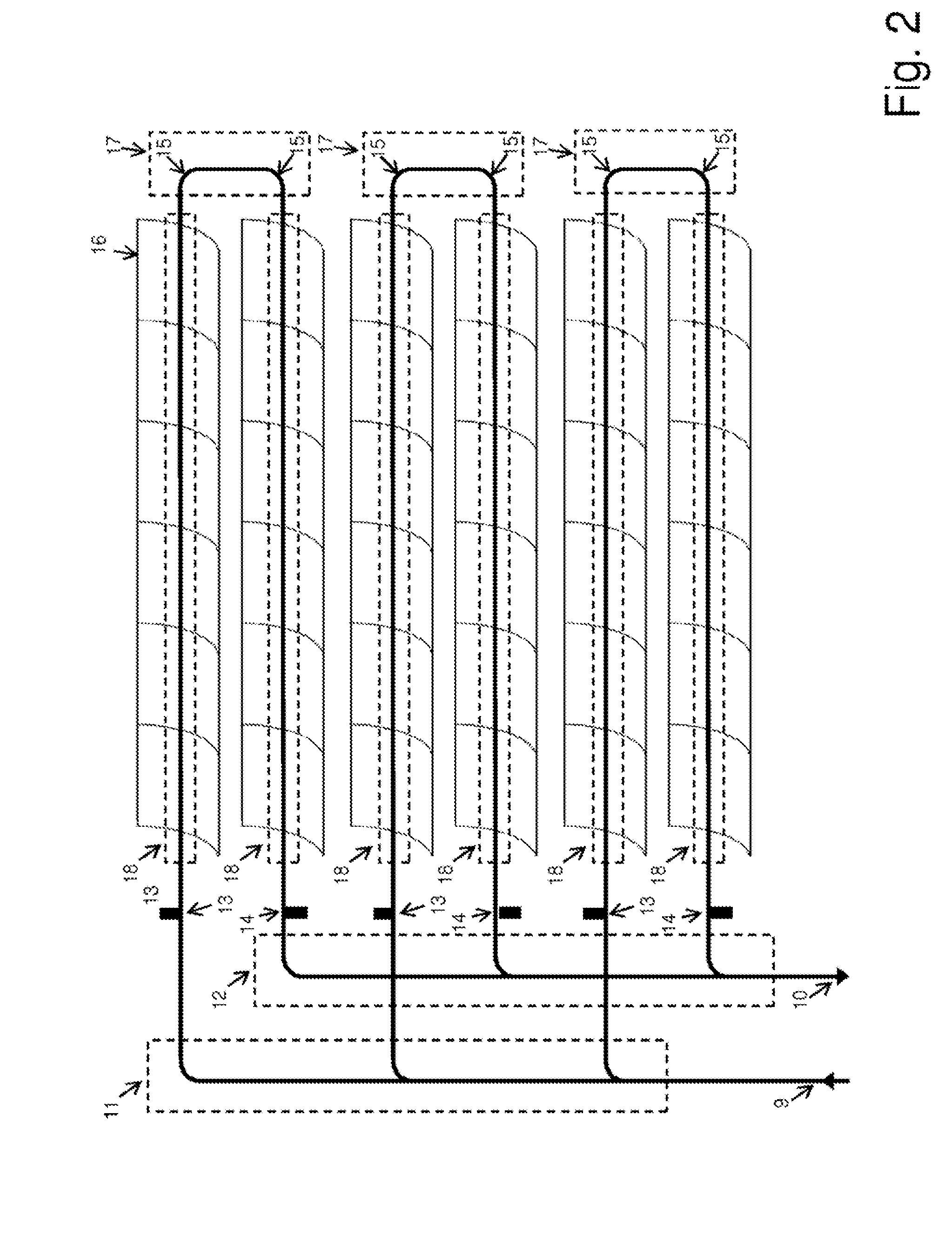
[0084]In various embodiments and / or usage scenarios, the illustrated embodiments are related to each other. For example, in some embodiments, solar heaters 8 of FIG. 1 are implemented using techniques as described by FIGS. 2, 3a-d, 4, and 5a-b. For another example, in some embodiments, solar receiver line 20, of FIGS. 3a-b, is representative of solar receiver 18 of FIG. 2.


PUM


Abstract

Solar energy generates steam in a “once-through” configuration without recirculation, with closely managed steam quality, to produce wet steam from high-contaminant feed water without scaling or fouling. Feed water is pressurized, preheated, and evaporated in a series of pipes exposed to concentrated solar energy to produce a water-steam mixture for direct distribution to an industrial process such as enhanced oil recovery or desalination. Water flow rates are managed based on measurements of solar energy and steam production to manage variations in the solar energy. Steam generator piping system uses continuous receiver pipe that is illuminated by segmented parabolic mirrors enabled to track the sun. Provisions for steam generator piping recurring maintenance are provided. Thermal energy from hot condensate and/or from low quality steam is recaptured and warms inlet water.

Description

CROSS-REFERENCE TO RELATED APPLICATIONS[0001]This application is a continuation of U.S. patent application Ser. No. 13 / 902,492, filed on May 24, 2013, which is a continuation of U.S. patent application Ser. No. 13 / 576,652, filed Aug. 1, 2012, which is a 371 U.S. National Phase Entry of PCT / US2011 / 42906, filed Jul. 3, 2011. PCT / 2011 / 42906, filed Jul. 3, 2011, claims benefit of priority to U.S. Provisional Application No. 61 / 361,512, filed Jul. 5, 2010, and U.S. Provisional Application No. 61 / 445,545, filed Feb. 23, 2011, which are both incorporated herein by reference. Priority benefit claims for this application are made in the accompanying Application Data Sheet, Request, or Transmittal (as appropriate, if any). To the extent permitted by the type of the instant application, this application incorporates by reference for all purposes the following applications, all commonly owned with the instant application at the time the invention was made:[0002]U.S. Provisional Application (Doc...

Claims


Application Information

Patent Timeline
Patent Type & Authority Applications(United States)
IPC IPC(8): F24J2/12F24S10/40F24S10/70F24S20/20F24S23/70F24S23/71F24S50/20
CPCF24J2/12F22B1/006B08B3/08B08B9/055F28G1/12F24S10/70F24S20/20F24S23/74F24S30/425F24S40/20F24S40/80F24S2023/834Y02E10/44Y02P80/20Y02A20/142F24S10/40F24S10/742F24S23/71Y02E10/40
Inventor O'DONNELL, JOHN SETELVON BEHRENS, PETER EMERYHEISLER, STUART M.
Owner GLASSPOINT SOLAR
Why Eureka
Try Eureka