Pneumatic fracturing method and system for exploiting shale gas

a shale gas and pneumatic fracturing technology, applied in earth-moving drilling, fluid removal, borehole/well accessories, etc., can solve the problems of low degree of shale gas fracturing, inapplicable hydraulic fracturing technology to water shortage or water deficit areas, and tremendous water consumption, so as to facilitate the desorption of shale gas, enhance the activities of oil and gas molecules, and improve the permeability of shale formation

Inactive Publication Date: 2014-11-06
SICHUAN UNIV
View PDF1 Cites 2 Cited by
  • Summary
  • Abstract
  • Description
  • Claims
  • Application Information

AI Technical Summary

Benefits of technology

[0009]In view of the above-described problems, it is one objective of the invention to provide a pneumatic fracturing method and a system for exploiting shale gas for facilitating the shale gas exploitation in water shortage or deficit areas, improving recovery factor of the shale gas, and protecting the ecological environment.
[0022]2. As the method of the invention utilizes the high temperature and high pressure gases to make brittle fatigue failures occur in the shale formation under the action of alternative different pressures thereby resulting in fissures, thus, the tight micro pores in the shale formation grow and communicate with each other. The permeability of the shale formation is largely improved, the desorption of the shale gas is facilitated, activities of oil and gas molecules are enhanced, that is, the filtration and the dissipation capacity of the oil and gas molecules are increased, thereby increasing the recovery efficiency of the shale gas.
[0024]4. The system of the invention is capable of controlling the aptitude and frequency of the compressed gas to continuously enlarge the fissures in the shale formation and widespread the fissures to deep regions, thereby broadening the channel and the range of the eruption of the shale oil and gas.

Problems solved by technology

1) The water consumption is tremendous, so that the hydraulic fracturing technology is not applicable to water shortage or water deficit areas where the shale gas distributes.
2) Although the hydraulic fracturing has a high fracturing pressure, with a maximum of 140 megapascal. However, main cracks forming under the action of the hydraulic fracturing has a limited number and the form thereof is single, which result in a low degree of fracturing of the shale formation. Besides, as the fluid has a large surface tension and molecules and poor permeability, it is difficult to introduce the fluid into the compact fissures in the shale formation or to improve the permeability of oil-gas in the shale formation, thereby resulting in low recovery factor.
3) The chemical additives and the shale gas (mainly methane) in the fracturing fluid enter the ground water, seriously pollute the ecological environment, and seriously restrict the exploitation of the shale gas.

Method used


Image

  • Pneumatic fracturing method and system for exploiting shale gas
  • Pneumatic fracturing method and system for exploiting shale gas
  • Pneumatic fracturing method and system for exploiting shale gas

Examples


example 1

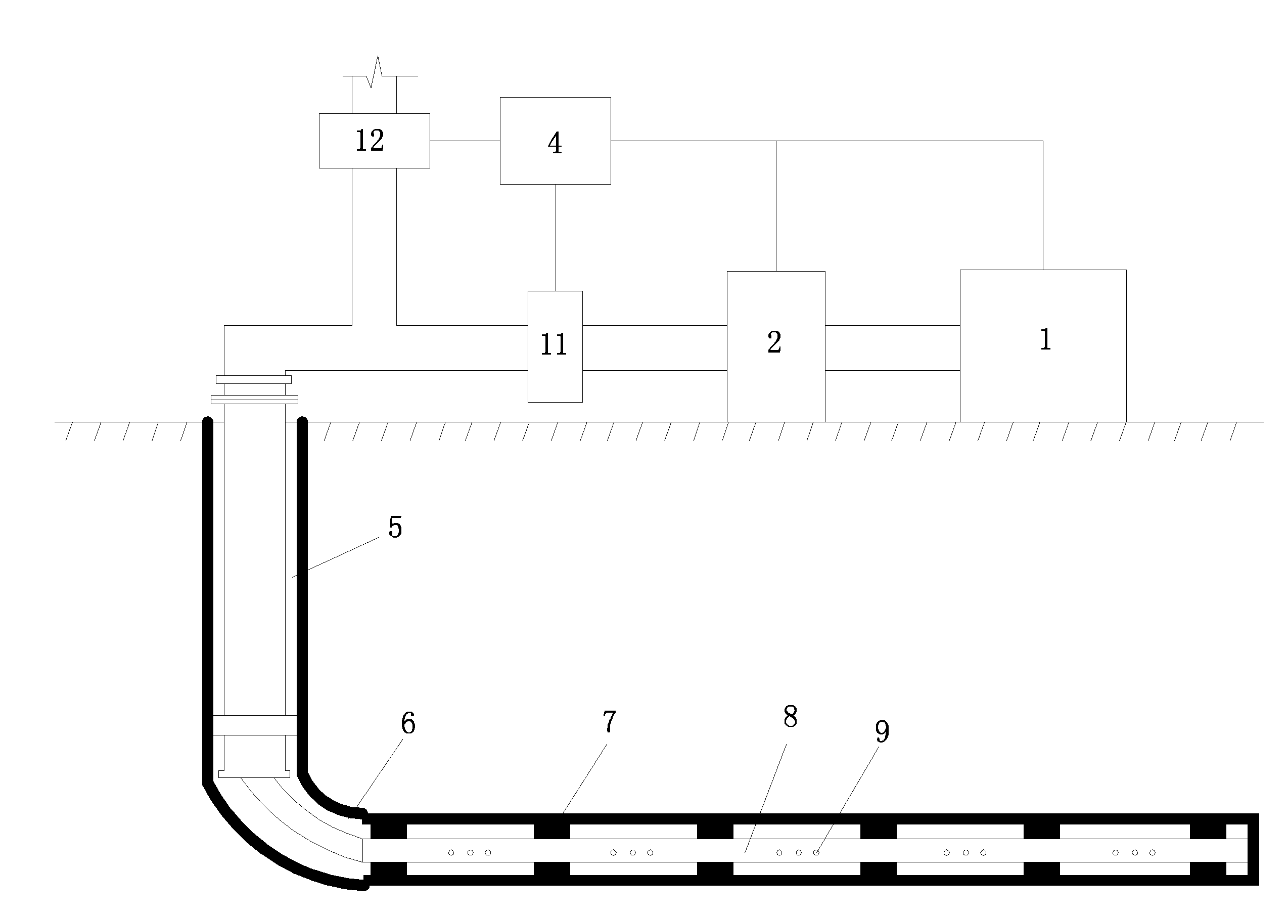
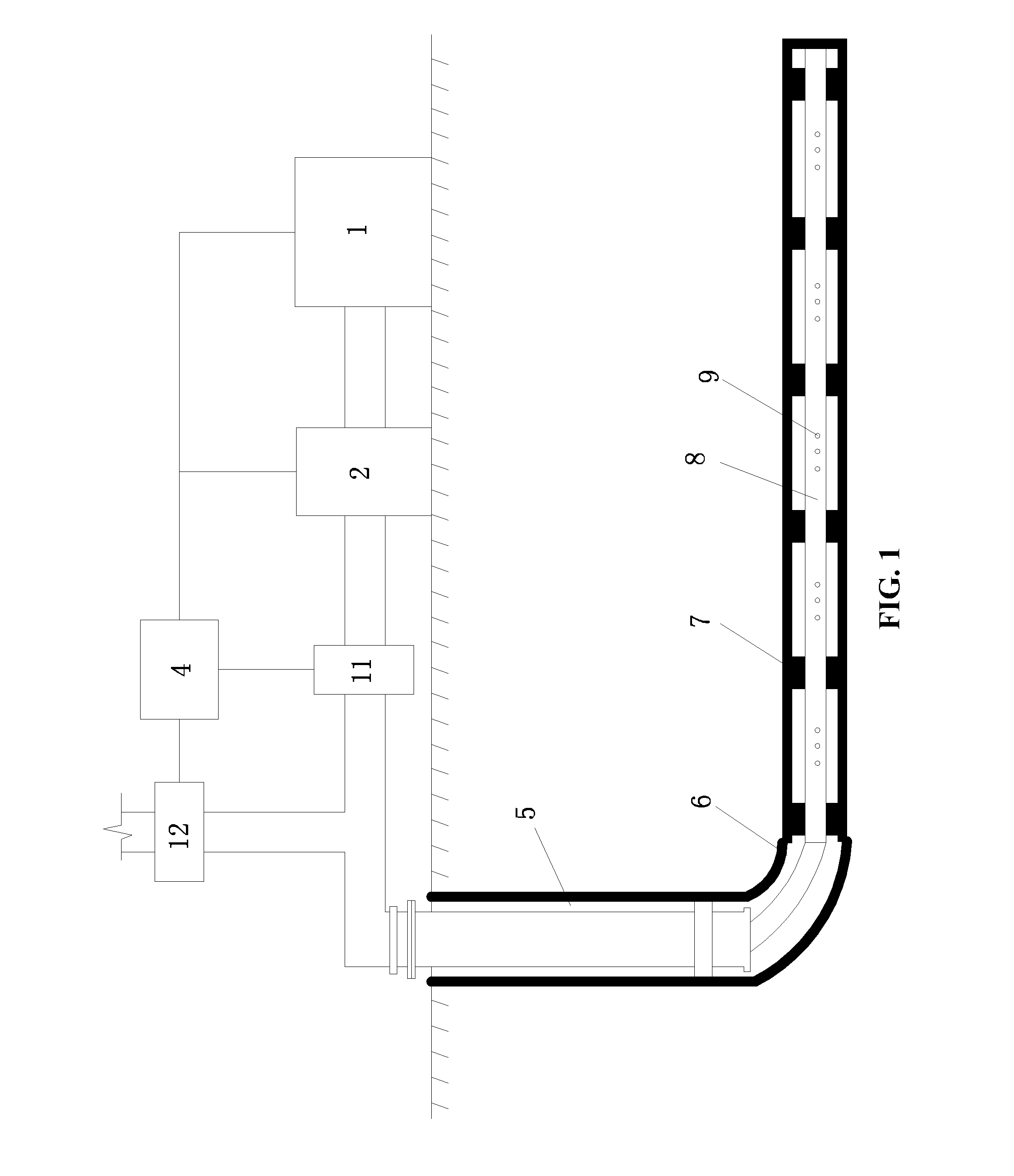
[0045]A pneumatic fracturing system is shown in FIG. 1, and a pneumatic fracturing method for exploiting shale gas using the system employs compressed air of two different pressures to alternately act on a shale formation. The method is conducted as follows:

[0046]A) A vertical well 5 and a horizontal well 6 communicating with the vertical well 5 are drilled in the shale formation, and a gas transporting pipeline 8 having insulation property is installed in the vertical well 5 and the horizontal well 6. An outer diameter of the gas transporting pipeline 8 is smaller than an inner diameter of the vertical well 5 and an inner diameter of the horizontal well 6. Ventholes 9 are arranged on a wall of the gas transporting pipeline 8 installed in the horizontal well 6. An annular space forms between an inner surface of the horizontal well 6 and an outer surface of the gas transporting pipeline 8, and annular occluders 7 are arranged in the annular space at an interval of 30 m to form a plur...
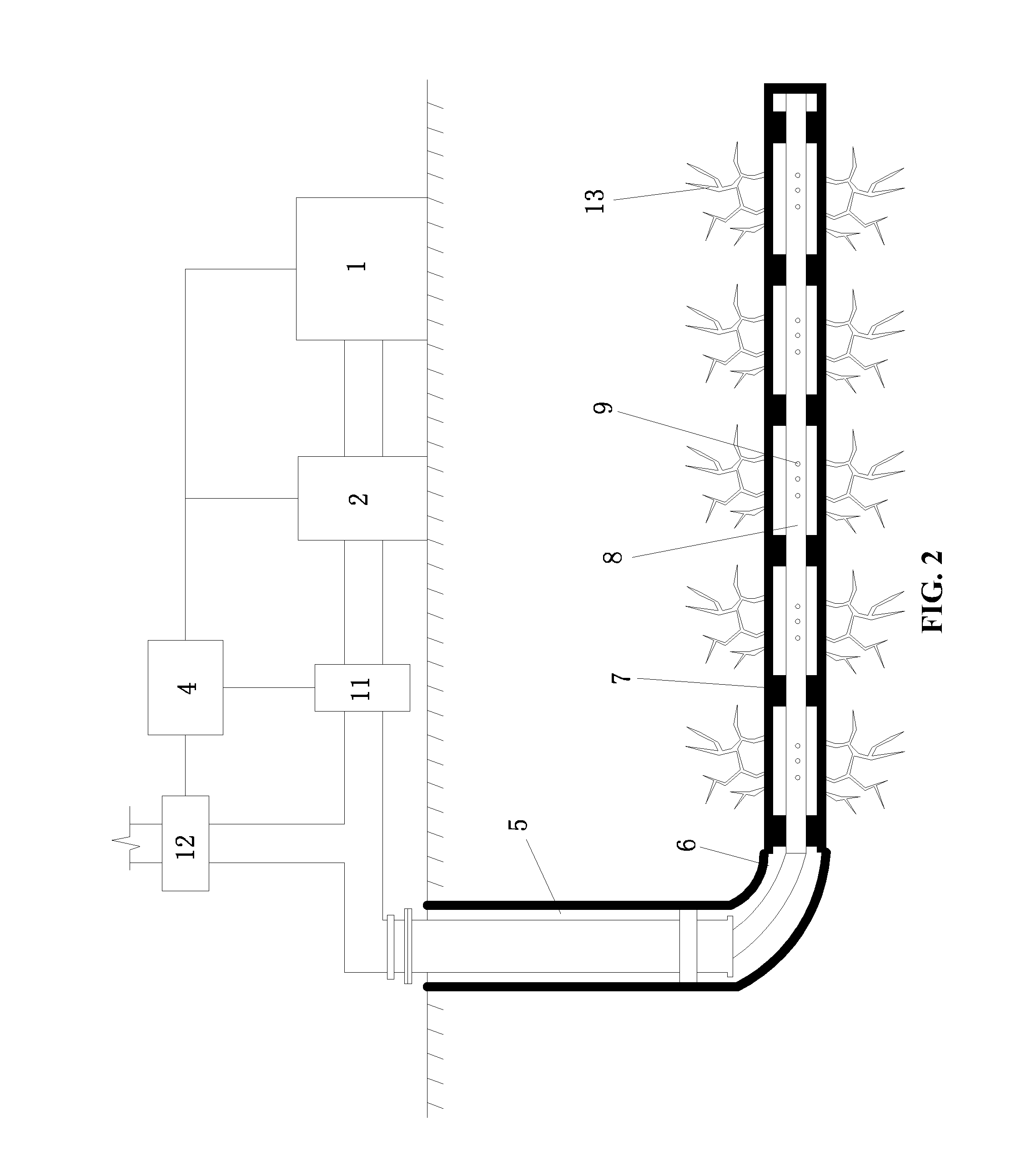
example 2

[0050]A pneumatic fracturing system is shown in FIG. 3, and a pneumatic fracturing method for exploiting shale gas using the system employs compressed carbon dioxide of two different pressures to alternately act on a shale formation. The method is conducted as follows:

[0051]A) A vertical well 5 and a horizontal well 6 communicating with the vertical well 5 are drilled in the shale formation, and a gas transporting pipeline 8 having insulation property is installed in the vertical well 5 and the horizontal well 6. An outer diameter of the gas transporting pipeline 8 is smaller than an inner diameter of the vertical well 5 and an inner diameter of the horizontal well 6. Ventholes 9 are arranged on a wall of the gas transporting pipeline 8 installed in the horizontal well 6. An annular space forms between an inner surface of the horizontal well 6 and an outer surface of the gas transporting pipeline 8, and annular occluders 7 are arranged in the annular space at an interval of 40 m to ...

example 3

[0055]A pneumatic fracturing system is shown in FIG. 5, and a pneumatic fracturing method for exploiting shale gas using the system employs compressed air of two different pressures to alternately act on a shale formation. The method is conducted as follows:

[0056]A) A vertical well 5 and a horizontal well 6 communicating with the vertical well 5 are drilled in the shale formation, and a gas transporting pipeline 8 having insulation property is installed in the vertical well 5 and the horizontal well 6. An outer diameter of the gas transporting pipeline 8 is smaller than an inner diameter of the vertical well 5 and an inner diameter of the horizontal well 6. Ventholes 9 are arranged on a wall of the gas transporting pipeline 8 installed in the horizontal well 6. An annular space forms between an inner surface of the horizontal well 6 and an outer surface of the gas transporting pipeline 8, and annular occluders 7 are arranged in the annular space at an interval of 50 m to form a plur...


PUM


Abstract

A pneumatic fracturing method for exploiting shale gas, the method including: 1) applying a compressed gas for a first period of time at a first pressure to a shale formation; 2) applying the compressed gas for a second period of time at a second pressure to the shale formation; and 3) repeating steps 1) and 2) to produce fissures in the shale formation. A temperature of the compressed gas is at least 80° C. A maximum pressure of the compressed gas is at least 25 megapascal, and a minimum pressure of the compressed gas is between ¼ and ⅓ of the maximum pressure.

Description

CROSS-REFERENCE TO RELATED APPLICATIONS[0001]This application is a continuation-in-part of International Patent Application No. PCT / CN2013 / 077007 with an international filing date of Jun. 8, 2013, designating the United States, now pending, and further claims priority benefits to Chinese Patent Application No. 201210188794.X filed Jun. 8, 2012. The contents of all of the aforementioned applications, including any intervening amendments thereto, are incorporated herein by reference. Inquiries from the public to applicants or assignees concerning this document or the related applications should be directed to: Matthias Scholl P.C., Attn.: Dr. Matthias Scholl Esq., 245 First Street, 18th Floor, Cambridge, Mass. 02142.BACKGROUND OF THE INVENTION[0002]1. Field of the Invention[0003]The invention relates to the field of shale gas exploitation, and more particularly to a pneumatic fracturing method and a system for exploiting shale gas.[0004]2. Description of the Related Art[0005]A typical...

Claims


Application Information

Patent Timeline
Patent Type & Authority Applications(United States)
IPC IPC(8): E21B43/16
CPCE21B43/168E21B43/26E21B43/24E21B43/247E21B43/2605
Inventor GAO, FENGXIE, HEPINGZHOU, FUBAOJU, YANGXIE, LINGZHILIU, YINGKEGAO, YANANLIU, JIANFENGZHANG, RU
Owner SICHUAN UNIV
Why Eureka
Try Eureka