Method and device for producing synthesis gas from biomass

a technology of synthesis gas and biomass, which is applied in the direction of combustible gas production, biofuels, gasifier mechanical details, etc., can solve the problems of reducing the efficiency of the plant and excreting steam

Inactive Publication Date: 2014-07-29
TETZLAFF KARL HEINZ
View PDF33 Cites 6 Cited by
  • Summary
  • Abstract
  • Description
  • Claims
  • Application Information

AI Technical Summary

Benefits of technology

[0012]It is the object of the invention to avoid the explained disadvantages in the generation of synthesis gas from biomass.
[0017]The tar content can be reduced even further if the pyrolysis gas is heated before entry into the fluidised bed of the synthesis gas reactor by a heating device or adding oxygen to temperatures of from 850° C. to 1600° C., preferably to temperatures of from 900° C. to 1300° C., particularly preferably to temperatures of from 950° C. to 1200° C. The tars in the pyrolysis gas will thereby be substantially broken down. If the temperature is selected to be higher than the ash melting point, it is advantageous to remove dust from the pyrolysis gas beforehand, otherwise a similarly large outlay for removing the molten ash is required as in entrained flow reactors.
[0020]The high-temperature pyrolysis may be preceded by a plurality of low-temperature pyrolyses, which facilitates exploitation of the sensible heat from the process.
[0024]It is advantageous for the pyrolysis gas to be fed through a catalyst bed before entry into the synthesis gas reactor. The catalyst bed may be arranged below the fluidised bed of the synthesis gas reactor. The catalyst may be selected so that tars and methane can preferably be converted into synthesis gas. The pyrolysis gas does not then need to be heated too greatly. For example, carrier-fixed transition metals such as nickel are suitable as catalysts. The catalyst may also remove ammonia from the superheated pyrolysis gas.
[0025]When processing the synthesis gas further, for example to form hydrogen, methane and higher hydrocarbons must be separated and fed back to the synthesis gas reactor. Mixing these gases with the heated pyrolysis gas leads to chemical quenching in the gas phase, which may be assisted catalytically. In this way, the incoming fluidisation gas is cooled and places less demands on the freedom from the dust and the design. The cooling may be assisted by adding cold gases.

Problems solved by technology

Excess steam would reduce the efficiency of the plant.

Method used


Image

  • Method and device for producing synthesis gas from biomass
  • Method and device for producing synthesis gas from biomass
  • Method and device for producing synthesis gas from biomass

Examples


Embodiment Construction

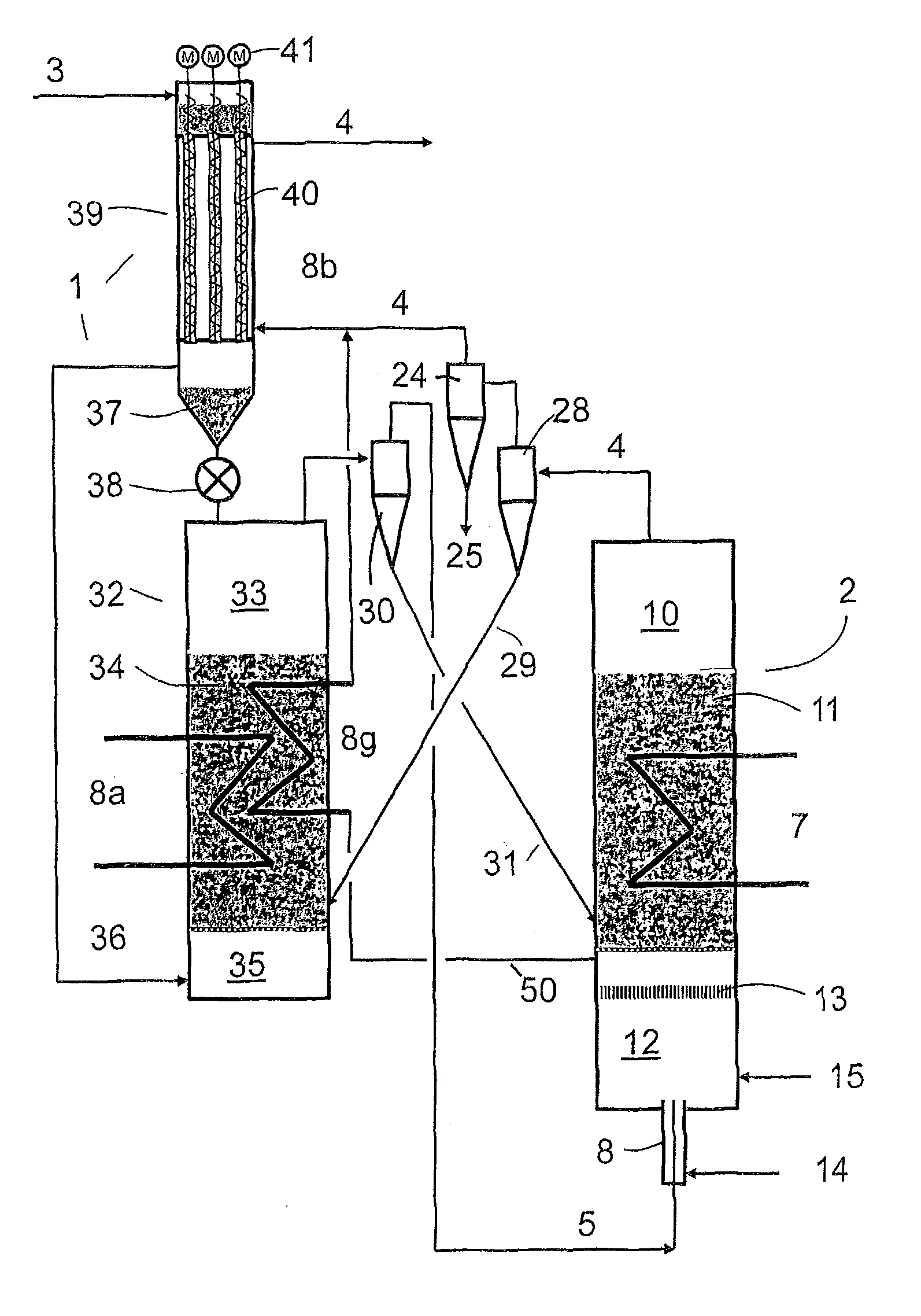
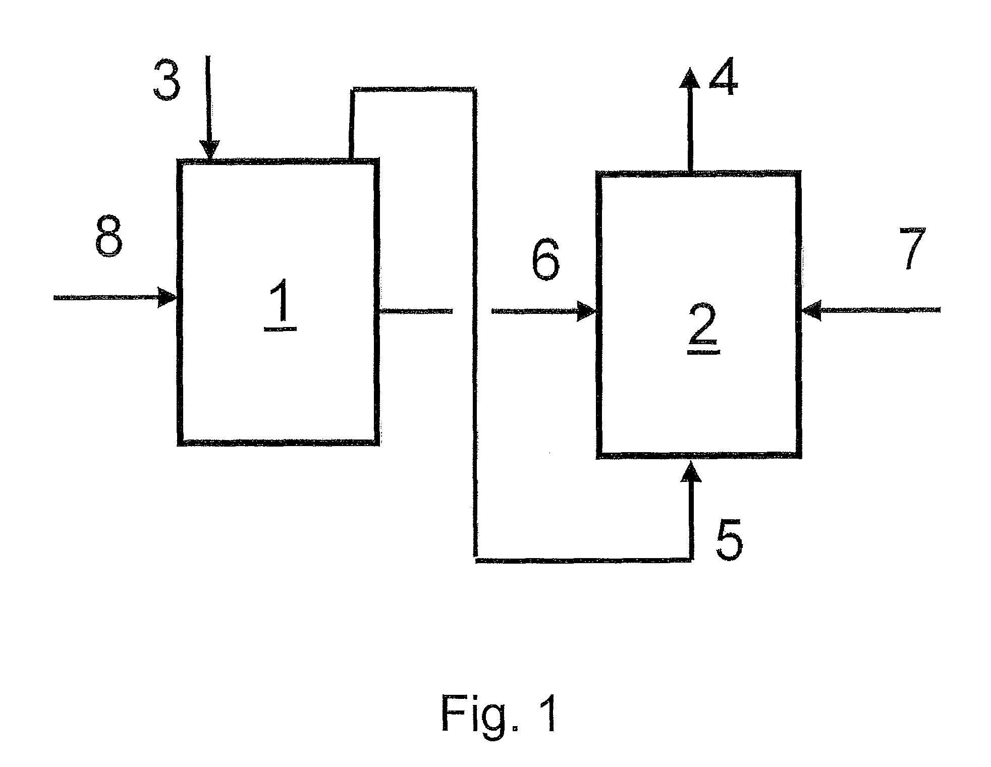
[0034]According to FIG. 1, the device according to the invention for producing synthesis gas from biomass consists of two reactors. In the reactor 1, the biomass 3 introduced is decomposed into pyrolysis coke and pyrolysis gas by supplying an amount of heat 8 or by partial oxidation. The pyrolysis coke 6 is introduced into the fluidised bed of a synthesis gas reactor 2. The pyrolysis gas 5 is used as fluidisation gas for the fluidised bed of the synthesis gas reactor 2. By supplying an amount of heat 7 into the synthesis gas reactor or by partial oxidation, the synthesis gas 4 is generated from the pyrolysis coke 6 and the pyrolysis gas 5.

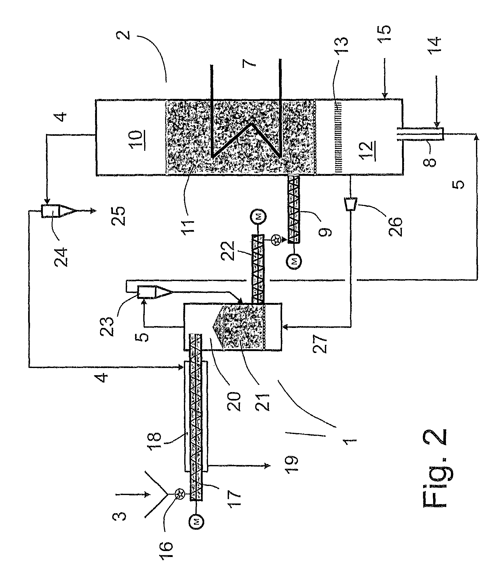
[0035]FIG. 2 shows a more detailed representation of the concept according to the invention. The pyrolysis 1 consists of a plurality of devices for conveying and pyrolysing the biomass introduced. The biomass 3 is introduced through a rotary valve 16 into a screw conveyor 17 that has a heating jacket 18, through which the hot synthesis gas 4 flows....


PUM

PropertyMeasurementUnit
pressureaaaaaaaaaa
pressureaaaaaaaaaa
thermal poweraaaaaaaaaa

Abstract

A method and a device for producing synthesis gas from biomass, wherein the biomass is decomposed into pyrolysis coke and pyrolisis gas in at least one pyrolisis reactor, the pyrolysis coke is introduced into the fluidized bed of a synthesis gas reactor and the pyrolysis gas is used as fluidization gas for the synthesis gas reactor.

Description

BACKGROUND OF THE INVENTION[0001]1. Field of the Invention[0002]The invention relates to a method and a device for the thermochemical production of synthesis gas from energy sources containing carbon, in particular from biomass.[0003]2. Description of the Related Art[0004]Synthesis gas from biomass is the starting product for the future solar hydrogen economy, in which the hydrogen is delivered to the end customer by a pipeline. Owing to the high efficiency in the decentral conversion of hydrogen into electricity, a surplus of electricity is obtained for almost all end consumers. Electricity and heat thus have the same value in this heat-controlled economy. For this reason, the use of electrical energy to provide the enthalpy of reaction for the production of synthesis gas is economical. Since electricity is only tradeable to a limited extent in the event of an electricity surplus, solar electricity, for example from wind energy, must be converted by water electrolysis into hydrogen...

Claims


Application Information

Patent Timeline
Patent Type & Authority Patents(United States)
IPC IPC(8): C01B3/36
CPCC10B49/10C10J2300/094C10J2300/0956C10J2300/1253C10J2200/158C10J3/66C10B57/02Y02E50/14C10J2300/0916C10J3/482C10J2200/09C10J2300/1823C10B53/02C10J3/56C10J3/54Y02P20/145Y02E50/10
Inventor TETZLAFF, KARL-HEINZ
Owner TETZLAFF KARL HEINZ
Why Eureka
Try Eureka