
Process and Apparatus for Molding Composite Articles

a composite article and process technology, applied in the direction of mechanical vibration separation, manufacturing tools, drawing profiling tools, etc., can solve the problems of porosity of parts made from vartm processes, difficult degassing, and neutral pressure on the bag

Active Publication Date: 2014-11-06
HURDLE ERIC
View PDF19 Cites 10 Cited by
  • Summary
  • Abstract
  • Description
  • Claims
  • Application Information

AI Technical Summary

Benefits of technology

The patent text describes a process and apparatus for molding composite articles using ultrasonic sound waves to vaporize resin in the reinforcing materials. This process improves the compaction of fibers and reduces porosity in the final article. The vacuum bag in the molding apparatus has additional degassing vacuum ports to maximize degassing and bleeding of the matrix. The process allows for higher compaction of fibers due to the vibration of wet reinforcing materials, resulting in a more compact and cost-effective article.

Problems solved by technology

After impregnation of the reinforcing fibers with the matrix, the pressure on the bag becomes neutral and degassing become difficult.
One of the problems of composite parts made from VARTM processes is the porosity.
Indeed, despite due care, the impregnation of the reinforcing materials with the matrix is never perfect and the resulting composite part typically contains porosities such as voids and gas bubbles around fibers and in the matrix.
Though porosities are generally not a major problem in the automotive and marine industries, they are a significant problem for the aerospace industry.
Unfortunately, current RTM, VARTM, even A-VARTM processes are not able to produce composite parts with the requisite limited amount of porosities suitable for the aerospace market.
However, the pre-impregnated process is excessively expensive.
In addition, the pre-impregnated process requires a pressurized autoclave which is very expensive, particularly for large composites parts.

Method used


Image

  • Process and Apparatus for Molding Composite Articles
  • Process and Apparatus for Molding Composite Articles
  • Process and Apparatus for Molding Composite Articles

Examples


Embodiment Construction

[0023]A novel process and related apparatus for molding composite articles will be described hereinafter. Although the invention is described in terms of specific illustrative embodiments, it is to be understood that the embodiments described herein are by way of example only and that the scope of the invention is not intended to be limited thereby.

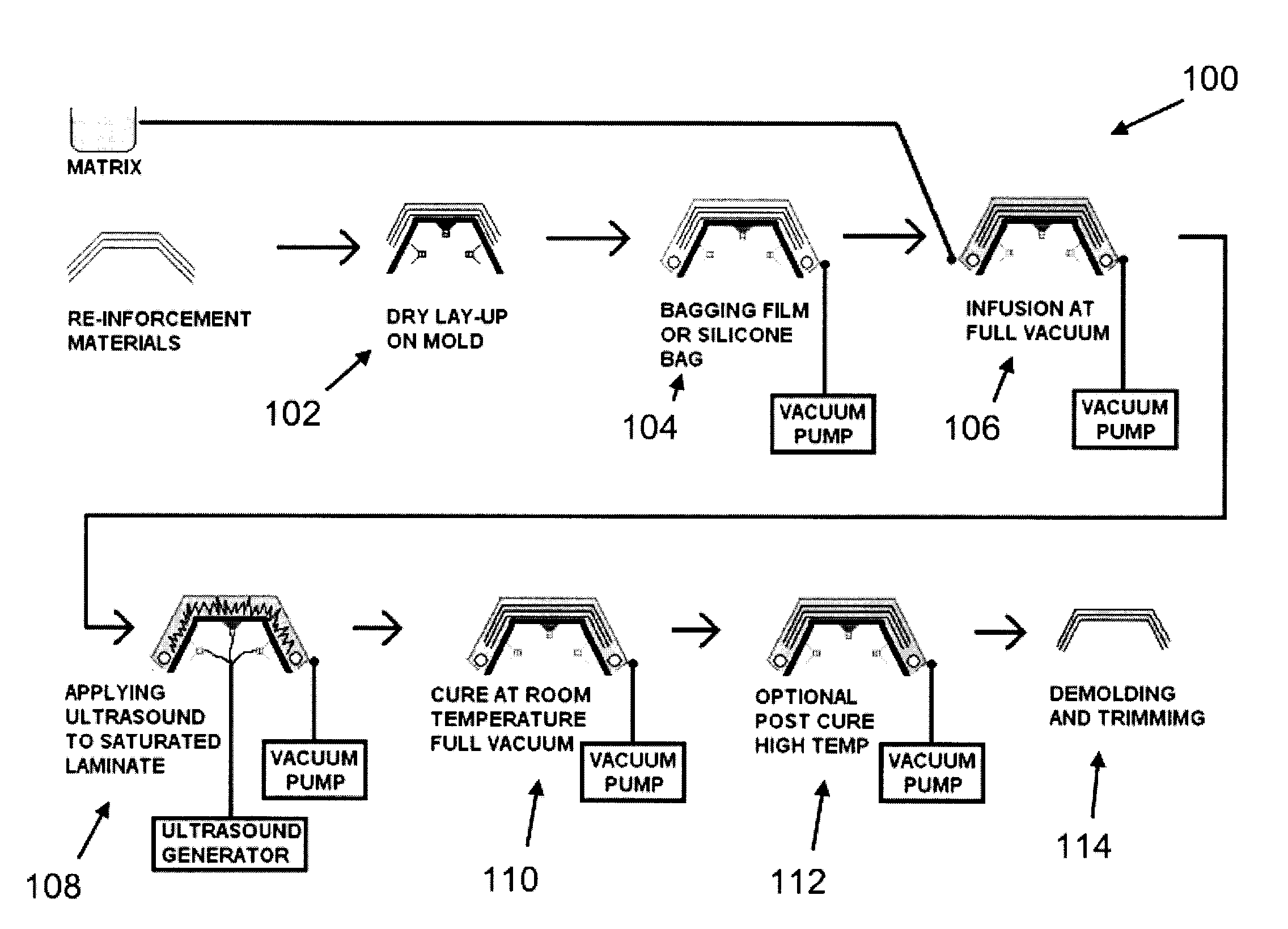
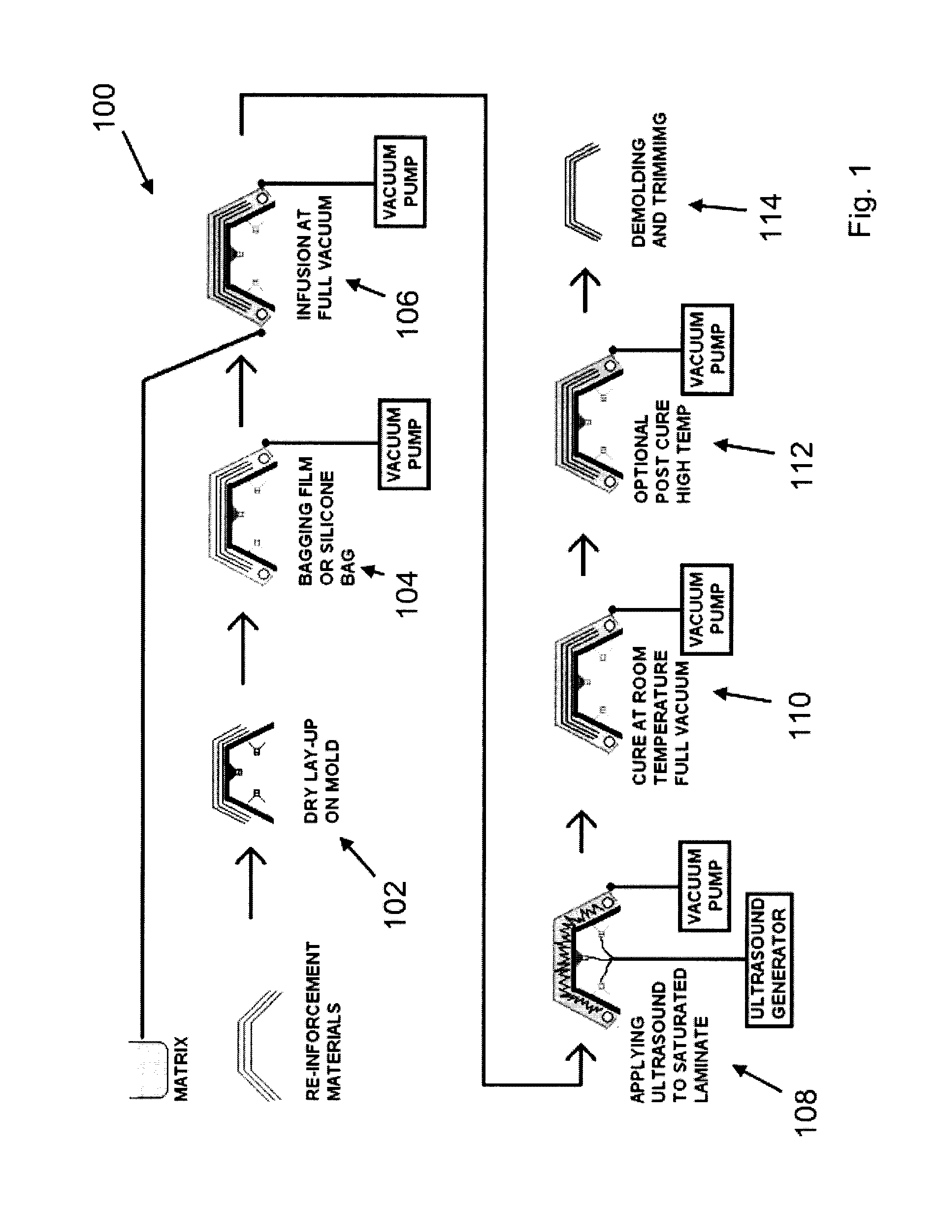
[0024]Referring first to FIG. 1, a flow-chart depicting an embodiment of a process 100 to mold composite articles in accordance with the principles of the present invention is shown.

[0025]In the present embodiment, the process 100 is mostly based on a A-VARTM process. Hence, the process 100 typically comprises the placement of reinforcing materials on a mold which is in the shape of the desired article (at 102). In the present embodiment, several types of reinforcing materials can be used. For instance, glass fibers, carbon fibers, glass fiber fabric, carbon fiber fabric, etc.

[0026]Next, once the reinforcing materials are properly positio...


PUM

PropertyMeasurementUnit
Thicknessaaaaaaaaaa
Frequencyaaaaaaaaaa
Vacuumaaaaaaaaaa

Abstract

A method and an apparatus for molding composite articles are disclosed. The method generally involves the saturation of reinforcing fibers (e.g. glass fibers, carbon fibers, etc.) with a matrix (e.g. resin, epoxy, cyanate ester, vinyl ester, polyester, etc.) in / on a mold using a conventional resin transfer molding (“RTM”) process (e.g. “RTM-light”) or a vacuum assisted resin transfer molding (“VARTM”) process (e.g. advanced VARTM or “A-VARTM”), and, once saturation is completed, the vibration of the matrix-infused fibers using controlled ultrasonic sound waves transmitted through the mold. By vibrating the matrix-infused fibers with the ultrasonic sound waves, the method and apparatus allow voids present between fibers to be closed and localized pockets of gases to be dislodged and degassed, and also allow the fibers to compact, thereby producing composite articles with reduced porosity and higher compaction.

Description

CROSS-REFERENCE TO RELATED APPLICATIONS[0001]The present patent application claims the benefits of priority of U.S. Provisional Patent Application No. 61 / 561,521, entitled “Apparatus and Method for the Controlled Ultrasonic Resin Infusion of Composite Articles” and filed at the United States Patent and Trademark Office on Nov. 18, 2011, the content of which is incorporated herein by reference.FIELD OF THE INVENTION[0002]The present invention generally relates to the field of resin transfer molding (“RTM”) processes and vacuum assisted resin transfer molding (“VARTM”) processes used for molding composite articles, and more particularly relates to advanced vacuum assisted resin transfer molding (“A-VARTM”) processes.BACKGROUND OF THE INVENTION[0003]There are many industries producing fiber-reinforced resin composite parts. For instance, composite parts are commonly used in the automotive, marine, industrial, and aerospace industries.[0004]Depending on the requirements of each industry...

Claims


Application Information

Patent Timeline
IPC IPC(8): B29C70/44B29C70/48
CPCB29C70/44B29C70/48B29C70/54B29C70/443B29C35/0261B29C37/0064
Inventor HURDLE, ERIC
Owner HURDLE ERIC
Learn More