Extreme environment heat exchanger

a heat exchanger and extreme environment technology, applied in the field of heat exchangers, can solve the problems that the machining of such extreme environment heat exchanger components becomes exceptionally difficult, and achieve the effect of reducing the rate of heat transfer, effectively concentrating heat within the coil, and minimizing the thermal expansion of the surrounding metal pip

Active Publication Date: 2014-11-13
RTX CORP
View PDF9 Cites 10 Cited by
  • Summary
  • Abstract
  • Description
  • Claims
  • Application Information

AI Technical Summary

Benefits of technology

[0010]Additionally, a metal coil seal may be secured between the outer surface of the heat transfer layer and the interior surface of the metal pipe. The coil seal is not bonded to the exterior surface of the heat transfer layer. The coil seal overlaps itself and therefore enables differential thermal growth or physical expansion of the coil between the heat transfer layer and the metal pipe in directions parallel to, perpendicular to, and rotationally about an axis of fluid flow within the hot fluid conduit. This minimizes thermal expansion of the surrounding metal pipe by effectively concentrating heat within the coil and reducing a rate of heat transfer into the metal pipe. The coil seal may also serve as second portions of a plurality of portions of cool fluid passages defined within the exterior surface of the heat transfer layer. In this embodiment, most of the heat transferred from the hot fluid moves into the cool fluid flowing through the cool fluid passages, while the coil seal expands longitudinally, axially and rotationally about itself, thereby serving to protect the surrounding, circumferentially displaced metal pipe from thermal expansion. The metal coil seal may also be configured to be coextensive with the heat transfer layer.
[0011]In yet another embodiment of the disclosure, the extreme environment heat exchanger includes a plurality of metal pipes, wherein each metal pipe defines a complete cool fluid passage. Each metal pipe is also secured adjacent to and coextensive with the heat transfer layer. A further aspect of this embodiment includes the exterior surface of the heat transfer layer defining a plurality of channels configured so that each of the plurality of metal pipes is secured within each of the plurality of channels to increase a rate of heat transfer between the heat transfer layer and the cool fluid passages defined by the metal pipes. Additionally, the metal pipes may be bonded within the channels to further increase a rate of heat transfer, so that the metal pipes, heat transfer layer and the hot fluid conduit defined by the ceramic matrix composite form an integral extreme environment heat exchanger.
[0012]An additional aspect of the disclosure includes a hot fluid conduit defined by a ceramic matrix composite and surrounded by a coextensive layer of hardenable material having a high thermal conductivity forming a heat transfer layer, wherein the heat transfer layer also defines a plurality of heat discharge extensions extending from the exterior surface of the heat transfer layer and away from the hot fluid conduit. The heat discharge extensions may take the form of one of fins and pins. Such fin-shaped discharge extensions may be continuous or discontinuous and may extend in a direction away from the heat transfer layer and generally parallel to a longitudinal axis of flow of the hot fluid through the ceramic matrix composite tube. Additionally, the heat discharge extensions may extend along a non-linear, tortuous path so that the heat discharge extensions make the cooling fluid follow a greater distance per unit of hot fluid flow to increase an amount of heat transfer to the cooling fluid and thereby increase an efficiency of the heat exchanger. In other words, the more effective the discharge extensions are in disrupting laminar cooling fluid flow and creating turbulent cooling fluid flow, the greater the potential heat transfer to the cooling fluid and the more efficient the heat exchanger.
[0014]This disclosure also includes a method of manufacturing the extreme environment heat exchanger. The method includes fabricating the hot fluid conduit by forming a ceramic matrix composite into an elongate form that defines the hot fluid conduit within the ceramic matrix composite. Next, a heat transfer layer made of the hardenable material is bonded to the ceramic matrix composite so that the heat transfer layer surrounds and is coextensive with the hot fluid conduit defined by the ceramic matrix composite. Then, the heat transfer layer is machined so that the heat transfer layer has about a uniform thickness surrounding the ceramic matrix composite, wherein the thickness of the heat transfer layer is between about one-half to ten times the wall thickness of the ceramic matrix composite tube. The wall thickness of the ceramic matrix composite tube will range in an exemplary embodiment from 0.05″ to 0.25″ (1.27 mm to 6.35 mm). The method may also include machining into the exterior surface of the heat transfer layer a plurality of channels having longitudinal axes parallel to a direction of flow of the hot fluid through the hot fluid conduit, so that heat discharge extensions are defined within the heat transfer layer. The machining of the heat transfer layer inlay be to define a plurality of channels instead of heat discharge extensions. Then the heat transfer surface and attached ceramic matrix composite may be secured within the metal pipe so that the metal pipe covers the plurality of channels in the exterior surface of the heat transfer layer to form a plurality of cool fluid passages. The method may also include inserting the coil seal between the exterior surface of the heat transfer layer and an interior surface of the metal pipe so that the coil seal covers the channels in the heat transfer layer, and the coil expands longitudinally, axially and rotationally about itself to absorb heat and minimize thermal expansion stress on the metal pipe.

Problems solved by technology

These disclosures confront the many difficulties of integrating high-temperature tolerant ceramic materials with metal components, wherein the ceramic and metal have substantially different coefficients of thermal expansion and likewise different responses to varying mechanical, chemical and other stresses common to extreme environment heat exchangers.
Machining of such extreme environment heat exchanger components becomes exceptionally challenging when it is necessary to extract heat from fluids reaching 3,000° F.

Method used


Image

  • Extreme environment heat exchanger
  • Extreme environment heat exchanger
  • Extreme environment heat exchanger

Examples


embodiment 30

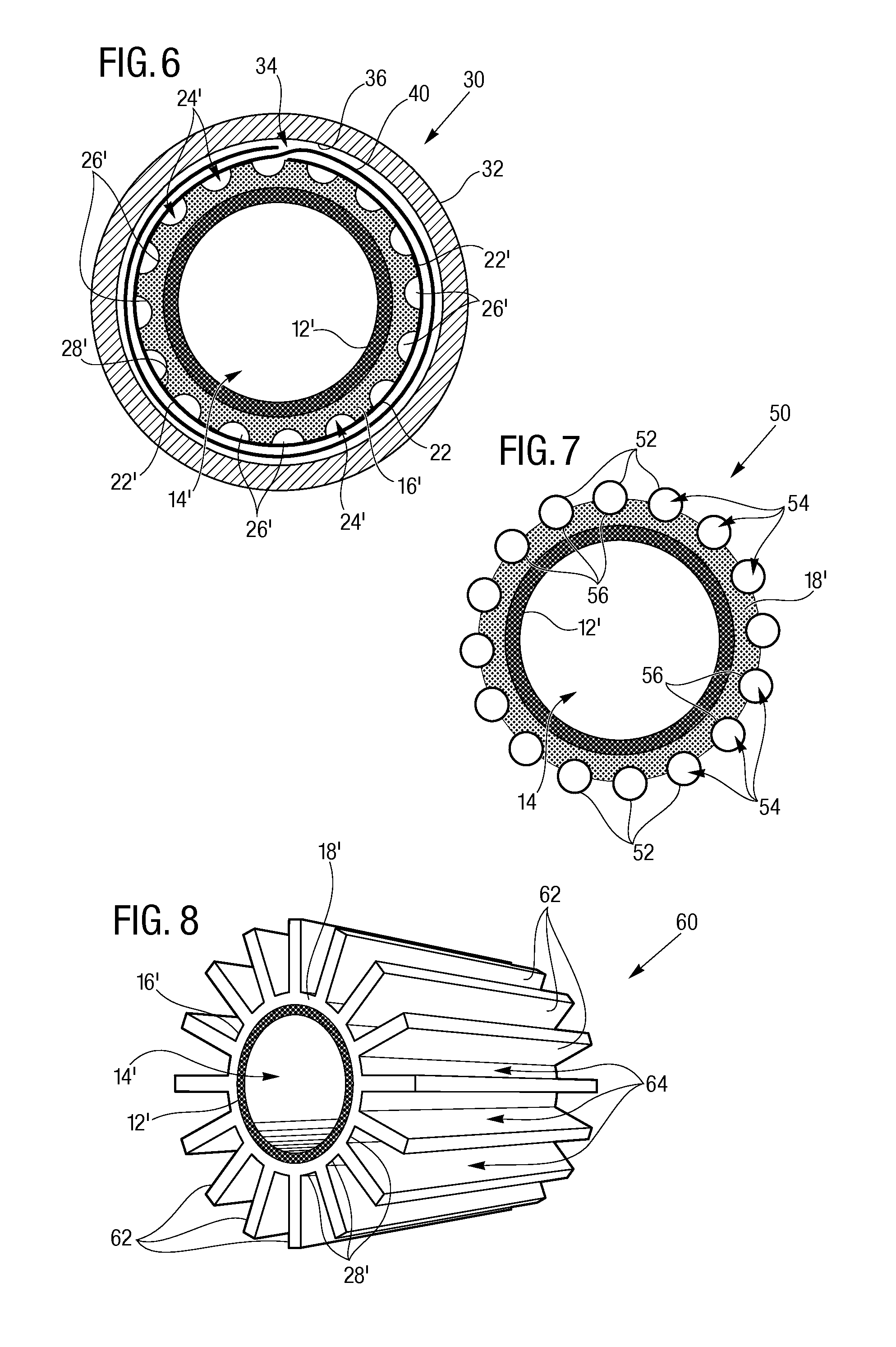
[0030]The displaced metal pipe embodiment 30 may also include a plurality of portions 26′ of cool fluid passages 24′ defined within the exterior surface 28′ of the heat transfer layer 16′. This increases the exterior surface area 28′ of the heat transfer layer 16′ exposed to a cooling fluid passing through the surrounding cool fluid passage 34 and / or the cool fluid passages 24′ that are defined between the metal pipe 32 and exterior surface 28′ of the heat transfer layer 16′.

[0031]The displaced metal pipe embodiment 30 may also include a metal coil seal 40 secured between the exterior surface 28′ of the heat transfer layer 16′ and the interior surface 36 of the metal pipe 32. The coil seal 40 may not be bonded or otherwise permanently secured to the exterior surface 28′ of the heat transfer layer 16′. The coil seal 40 (as shown in FIG. 6) overlaps itself and therefore enables differential thermal growth or physical expansion of the coil seal 40 between the heat transfer layer 16′ an...

embodiment 50

[0033]FIG. 7 shows a multi-tube embodiment 50 of the extreme environment heat exchanger 10. This embodiment 50 includes a plurality of metal pipes 52, wherein each metal pipe 52 defines a complete cool fluid passage 54. Each metal pipe 52 is also secured adjacent to and coextensive with the heat transfer layer 16′. A further aspect of this embodiment includes the exterior surface 28′ of the heat transfer layer 16′ defining a plurality of channels 56 configured so that each of the plurality of metal pipes 54 is secured within each of the plurality of channels 56 to increase a rate of heat movement between the heat transfer layer 16′ and the cool fluid passages 54 defined by the metal pipes 52. Additionally, the metal pipes 52 may be bonded within the channels 56 to further increase a rate of heat movement or transfer, so that the metal pipes 52, heat transfer layer 16′ and the hot fluid conduit 14′ defined by the ceramic matrix composite 12′ form an integral, multi-tube extreme envir...

embodiment 60

[0034]FIG. 8 shows a heat-discharge extension embodiment 60 of the extreme environment heat exchanger 10. This embodiment 60 includes a hot fluid conduit 14′ defined by a ceramic matrix composite 12′ and surrounded by a coextensive, heat transfer layer 16′ of hardenable material 18′. The heat transfer layer 16′ also defines a plurality of heat discharge extensions 62 extending from the exterior surface 28′ of the heat transfer layer 16′ and away from the hot fluid conduit 14′. A plurality of cool fluid passages 64 are defined between the heat discharge extensions 62. The heat discharge extensions 62 may take the form of fins and pins defined by the hardenable material 18 with the above described high thermal conductivity, such as metals including silicon, silver, copper, aluminum, nickel, nickel alloys. A length of extension of the heat discharge extensions away from and perpendicular to the hot fluid conduit 14′ may be between about one-half and about ten times a wall thickness of ...


PUM

PropertyMeasurementUnit
temperaturesaaaaaaaaaa
thicknessaaaaaaaaaa
thicknessaaaaaaaaaa

Abstract

The heat exchanger (10) includes a ceramic matrix composite (12) (stable at temperatures up to 1,650° C.) surrounding and defining a hot fluid conduit (14). A hardenable material (18) having a high thermal conductivity is formed into a heat transfer layer (16) surrounding the ceramic matrix composite (12). A metal pipe (20) is coextensive with the heat transfer layer (16) and defines at least a portion (22) of at least one cool fluid passage (24, 34, 54) defined adjacent to and in heat exchange relationship with the heat transfer layer (16) so that a fluid passing through the cool fluid passage (24, 34, 54) absorbs heat passing through the heat transfer layer (16) from the hot fluid passing through the hot fluid conduit (14).

Description

CROSS REFERENCE TO RELATED APPLICATION[0001]This Application claims the benefit of U.S. Provisional Patent Application Ser. No. 61 / 820,249 that was filed on May 7, 2013, entitled “EXTREME ENVIRONMENT HEAT EXCHANGER”.TECHNICAL FIELD[0002]The present disclosure relates to heat exchangers for transferring heat from a hot fluid conduit to a cool fluid passage, and in particular relates to a heat exchanger having a hot fluid conduit capable of tolerating fluids reaching temperatures up to three thousand degrees Fahrenheit (sixteen-hundred and fifty degrees Celsius) and / or corrosive fluids.BACKGROUND ART[0003]In the field of extremely high temperature tolerant materials it is known to use ceramic compounds combined with varying materials to transport high temperature fluids. For example, U.S. Pat. No. 2,405,075 that issued on Nov. 27, 1943 to Vollrath discloses a gas impervious ceramic tube capable of tolerating fluids reaching temperatures up to one-thousand five hundred degrees Fahrenhe...

Claims


Application Information

Patent Timeline
Patent Type & Authority Applications(United States)
IPC IPC(8): F28F21/04F28D7/10B21D53/02F28F1/00
CPCF28F21/04F28F1/003F28D7/10B21D53/02B23P15/26F28D7/0008F28D7/103F28F1/16F28F21/08F28F2265/26Y10T29/49361Y10T29/49377
Inventor JARMON, DAVID C.
Owner RTX CORP
Why Eureka
Try Eureka