Liquid atomizing device and liquid atomizing method

a technology of liquid atomizing device and liquid atomizing method, which is applied in the direction of spraying apparatus, liquid spraying apparatus, etc., can solve the problems of high price of atomizing nozzle device and unsuitable miniaturization, and achieve the effect of large-scale production

Inactive Publication Date: 2014-11-13
NOZZLE NETWORK
View PDF7 Cites 4 Cited by
  • Summary
  • Abstract
  • Description
  • Claims
  • Application Information

AI Technical Summary

Benefits of technology

[0037]According to this, it is possible to configure a small-sized cover body with a small number of simple parts which can be produced on a large scale. In this embodiment, the base portion, the first cover portion and the second cover portion may be configured using a single member, or they may be formed as independent members and they may be connected to each other. The first cover portion and the second cover portion may be configured using a single member, or they may

Problems solved by technology

However, since the atomizing nozzle device includes two two-fluid nozzle portions, the

Method used


Image

  • Liquid atomizing device and liquid atomizing method
  • Liquid atomizing device and liquid atomizing method
  • Liquid atomizing device and liquid atomizing method

Examples


embodiment 1

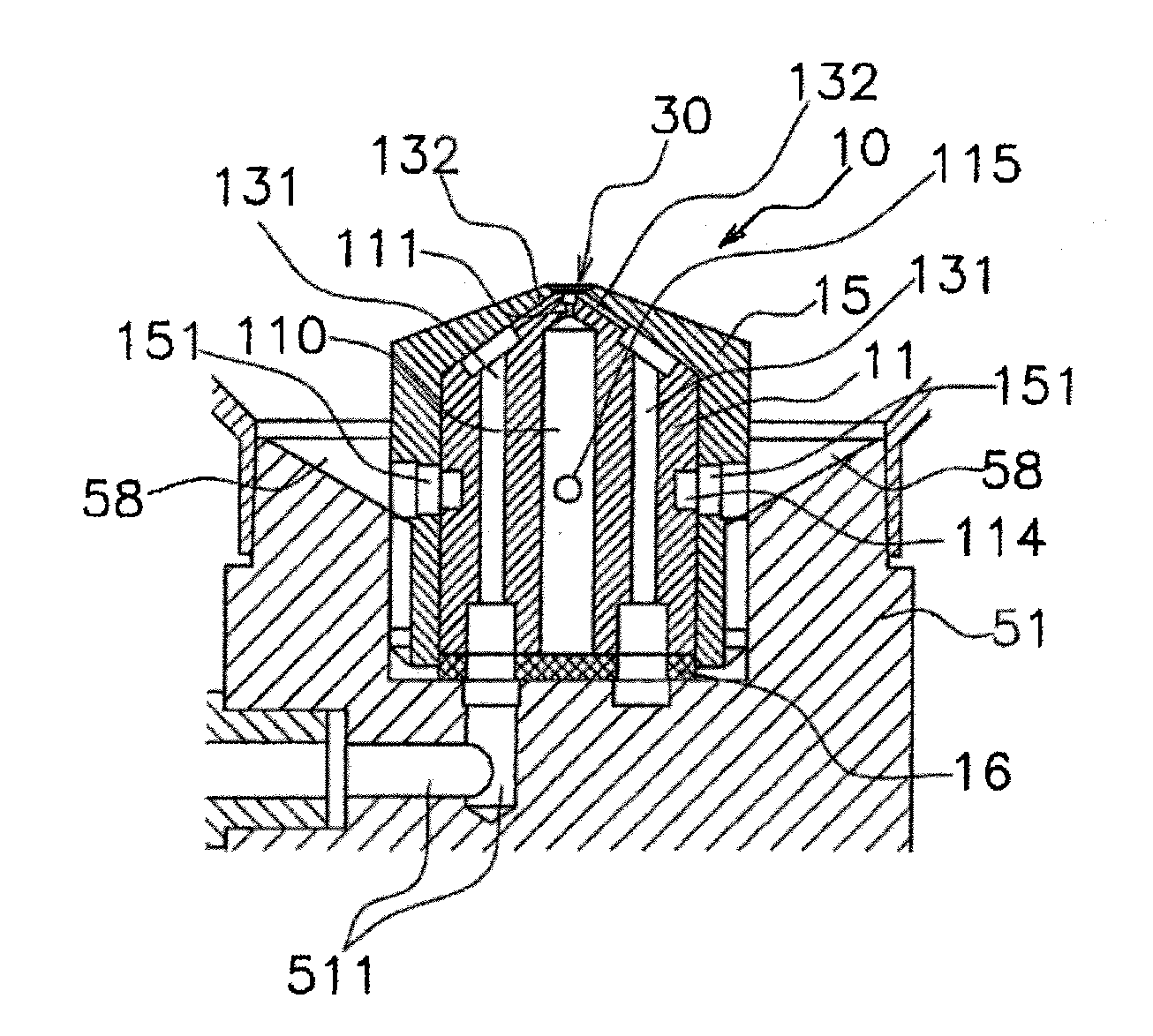
[0072]A liquid atomization device 1 having a nozzle body and a cover body of this embodiment will be described with reference to the drawings. FIG. 4A is a schematic sectional view of the entire liquid atomization device 1. The liquid atomization device 1 includes a nozzle body 10 which primarily atomizes, and a cover body 50 which secondarily atomizes for further micronizing mist sprayed from the nozzle body 10.

[0073]FIG. 4C is a schematic sectional view of the nozzle body 10. The nozzle body 10 includes a gas-liquid orifice portion 11 and a cap portion 15. A liquid passage 110 is formed at a center in an axial direction of the gas-liquid orifice portion 11. The liquid passage 111 includes a liquid orifice 111 in a direction of an outlet of the nozzle body. A depression (recess) 111a having a diameter greater than that of the liquid orifice 111 is formed in an outlet of the liquid orifice 111. As another embodiment, the depression 111a may not be provided, but if the depression 111...

embodiment 2

[0078]According to embodiment 2 shown in FIG. 6, a baffle portion 70 is provided in the liquid atomization device 1 of embodiment 1. The baffle portion 70 is placed in a cover body 50 from an interior of a first cover portion 52 to an interior of a suction cylinder 54 along a spray axial direction of a spray outlet 30. Sprayed mist is further micronized by the baffle portion 70.

[0079]FIGS. 7A to 7D are a front view, a side view, a bottom view and a plan view of the baffle portion 70. The baffle portion 70 includes a flange portion 71 formed on a bottom of the baffle portion 70, a long circular guide port 71, a hollow interior space 72, an opening outlet 74 in which two openings 74a and 74b are formed, and a ceiling surface 75. Although longitudinal directions of the openings 74a and 74b and the ceiling surface 75 are parallel to a longitudinal direction of the guide port 71 in FIGS. 7A to 7D, these directions are not especially limited to the above-described relation. Shapes, positi...

embodiments 1 and 2

Examples of Experiments of Embodiments 1 and 2

[0080]Spray characteristics were evaluated using the liquid atomization devices having the configurations shown in embodiments 1 and 2. A diameter of a cross section of the liquid orifice 111 was φ0.28, a diameter of a cross section of the depression 111a was φ0.5 mm, a cross section of the groove 132 had a V-shape, a width of the liquid orifice 111 was 0.18 mm, and a cut depth of the liquid orifice 111 was 0.3 mm. A cross section of gas flow is smaller than that of liquid. Air was used as gas, and water was used as liquid. A spray angle sprayed from the spray outlet of the nozzle body was set to 30°. In embodiments 1 and 2, the baffle portion was not used, and an air amount Qa (NL / min) of gas spray, an effective fog amount Qf (spray amount of mist from cover outlet), and an average particle diameter (SMD) of mist sprayed form the outlet when air pressure Pa of gas spray was changed to 0.05, 0.07 (MPa) were evaluated. Results of evaluati...


PUM


Abstract

A liquid atomization device includes a nozzle body. The nozzle body includes: a first gas spray portion and a second gas spray portion for spraying two gas flows; a liquid passage having a passage through which liquid flows by formation of the two gas flows sprayed by the first gas spray portion and the second gas spray portion; a gas-liquid mixture area where the gas flow sprayed from the first gas spray portion and the gas flow sprayed from the second gas spray portion are made to collide against liquid which flows from the liquid passage to atomize the liquid; and a spray outlet for spraying mist atomized in the gas-liquid mixture area to outside.

Description

TECHNICAL FIELD[0001]The present invention relates to a liquid atomizing device and a liquid atomizing method for atomizing liquid.BACKGROUND ART[0002]As conventional atomizing technique, there are a gas-liquid mix type (two-fluid type) technique, an ultrasound type technique, an extra-high voltage type (100 MPa to 300 MPa) technique, and a steaming type technique. According to a general two-fluid nozzle, gas and liquid are injected in the same injection direction, and liquid is miniaturized by a shear effect generated by accompanying flow of gas and liquid. Meanwhile, in fields of evaporation coating on a semiconductor wafer, medical equipment (e.g., suction machine), a liquid spray for cosmetic purposes, moisturizing liquid spray, and the like, it is required to atomize liquid with low energy.[0003]As one example of a gas-liquid mix type two-fluid nozzle, an atomizing nozzle device for producing minute particle mist is known (patent document 1). This atomizing nozzle device includ...

Claims


Application Information

Patent Timeline
IPC IPC(8): B05B7/04
CPCB05B7/0416B05B7/0012B05B7/0869B05B7/0425B05B7/0861B05B14/00Y02P70/10
Inventor ASAKAWA, HIROYOSHIKUGE, RYOTA
Owner NOZZLE NETWORK
Why Eureka
Try Eureka