
Coil component

a technology of coil components and components, applied in the direction of coils, transformers/inductance details, inductances, etc., can solve the problems of reducing the permeability of most coil components, increasing manufacturing costs, and suppressing the flow of magnetic flux loops, so as to prevent the performance of coil components from degrading

Inactive Publication Date: 2014-11-13
SAMSUNG ELECTRO MECHANICS CO LTD
View PDF5 Cites 25 Cited by
  • Summary
  • Abstract
  • Description
  • Claims
  • Application Information

AI Technical Summary

Benefits of technology

The invention provides a coil component with a layer that prevents degradation in its performance. Additionally, the invention aims to address increased costs and decreased productivity by allowing the existing process line, specifically photolithography, to be used for manufacturing the coil component.

Problems solved by technology

However, most of the coil components cannot but have reduced permeability since a periphery of a coil in which a current flows is enclosed by an insulating resin to be insulated from an external circuit.
However, the insulating layer provided between the upper and lower magnetic substrate has low permeability and large magnetic resistance, thereby suppressing a flow of the magnetic flux loop.
However, in order to produce the coil component having the above structure, in addition to the existing process, a process of machining a via hole and a process of inserting the magnetic core into the machined via hole need to be additionally carried out, such that an increase in manufacturing costs may be inevitable and the processes are hardly performed on the small coil components, such that productivity may be largely degraded.

Method used


Image

  • Coil component
  • Coil component
  • Coil component

Examples


Embodiment Construction

[0030]Various advantages and features of the present invention and methods accomplishing thereof will become apparent from the following description of exemplary embodiments with reference to the accompanying drawings. However, the present invention may be modified in many different forms and it should not be limited to exemplary embodiments set forth herein. These exemplary embodiments may be provided so that this disclosure will be thorough and complete, and will fully convey the scope of the invention to those skilled in the art.

[0031]Terms used in the present specification are for explaining exemplary embodiments rather than limiting the present invention. Unless explicitly described to the contrary, a singular form includes a plural form in the present specification. The word “comprise” and variations such as “comprises” or “comprising,” will be understood to imply the inclusion of stated constituents, steps, operations and / or elements but not the exclusion of any other constit...


PUM


Abstract

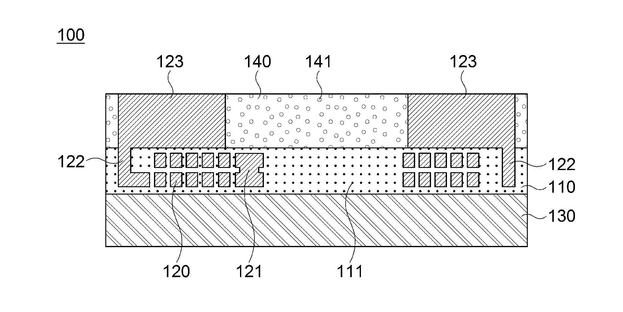
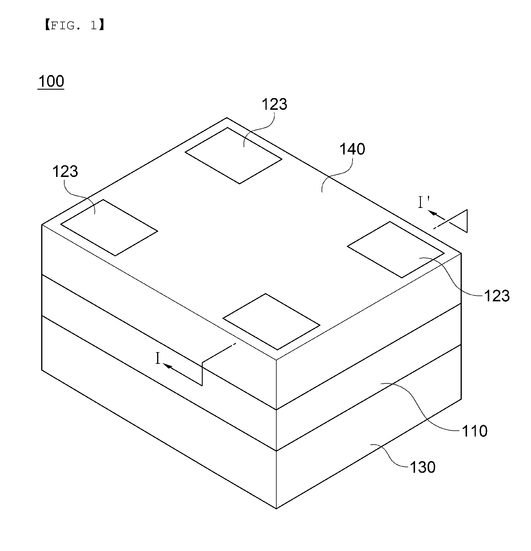
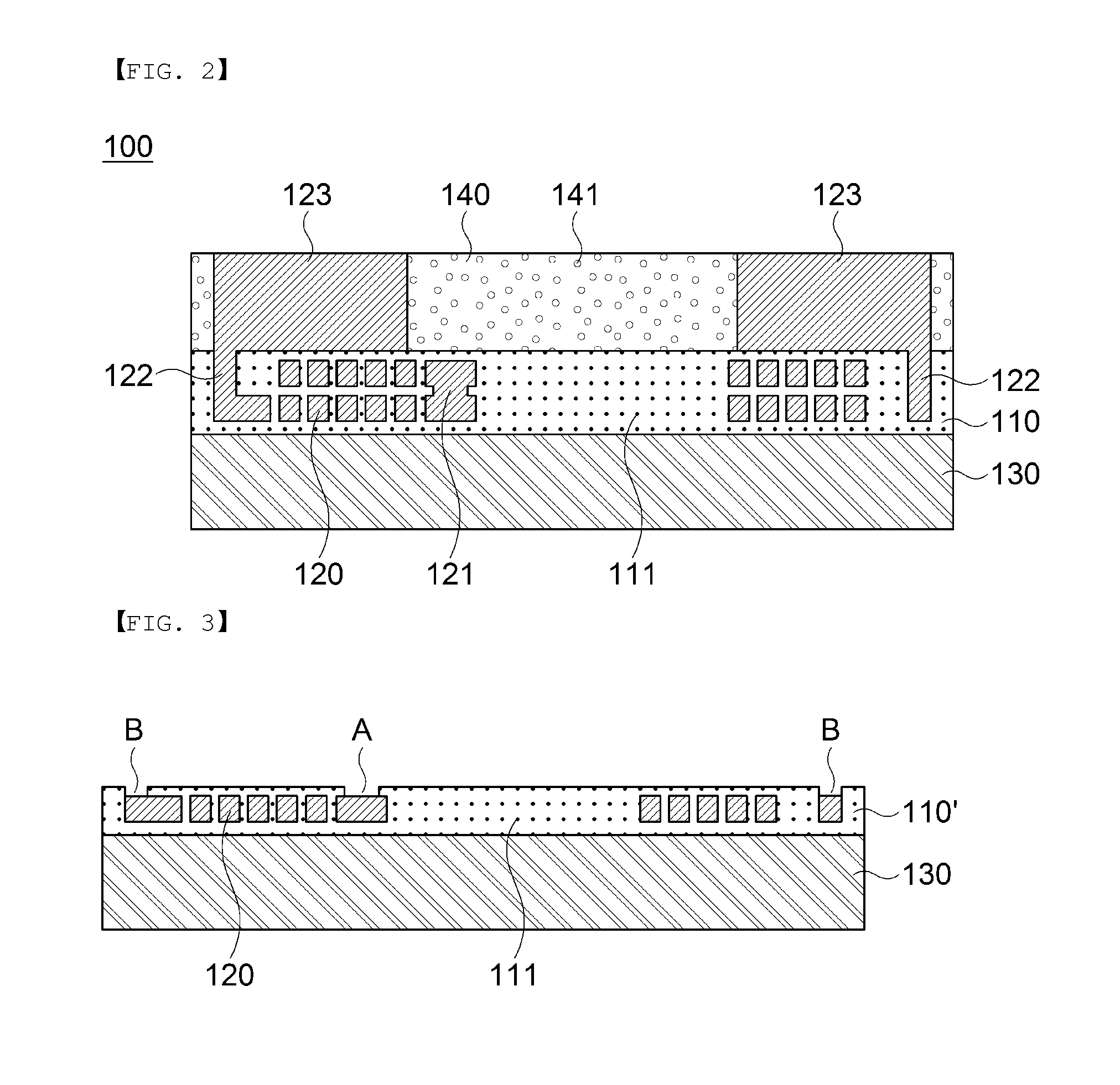
Disclosed herein is a coil component including: an insulating layer containing a ferrite powder and a coil electrode embedded in the insulating layer, in which a particle diameter of the ferrite powder is smaller than a wavelength of light which is used during an exposure process, thereby increasing permeability and improving an impedance characteristic.

Description

[0001]This application claims the benefit under 35 U.S.C. Section 119 of Korean Patent Application Serial No. 10-2013-0079061 entitled “Coil Component” filed on Jul. 5, 2013, which is hereby incorporated by reference in its entirety into this application.BACKGROUND OF THE INVENTION[0002]1. Technical Field The present invention relates to a coil component, and more particularly, to a coil component made of a high permeability material.[0003]2. Description of the Related Art[0004]A coil component is one of the important passive devices configuring an electronic circuit, along with a resistor and a capacitor, and has been mainly used in a power supply circuit such as a DC-DC converter within an electronic device or has been widely used as a component for removing noise or configuring an LC resonance circuit.[0005]Recently, in particular, as a data amount which is processed within the electronic device is increased, a high-speed signal transmission interface has been adopted, such that ...

Claims


Application Information

Patent Timeline
IPC IPC(8): H01F27/28H01F27/29
CPCH01F27/2804H01F27/29H01F17/0013H01F27/292H01F17/00H01F27/28
Inventor BAE, JUN HEELEE, SANG MOONWI, SUNG KWON
Owner SAMSUNG ELECTRO MECHANICS CO LTD
Learn More