Display device and display system

Inactive Publication Date: 2014-11-13
SHARP KK
View PDF5 Cites 18 Cited by
  • Summary
  • Abstract
  • Description
  • Claims
  • Application Information

AI Technical Summary

Benefits of technology

[0015]According to the display device and display system of the present invention, the detection device is controlled such that detection is performed during a horizontal blanking period in the display panel, and thus, the effect of noise and the like on the display panel due to the operation of the detection device can be mitigated. In particular, according to the display device and display system of the present inve

Problems solved by technology

Thus, touch panels are susceptible to receiving noise from the display panel, and a resultin

Method used


Image

  • Display device and display system
  • Display device and display system
  • Display device and display system

Examples


Example

Embodiment 1

[0025]First, Embodiment 1 of the present invention will be explained with reference to FIGS. 1 to 5.

[0026](Configuration of Display System)

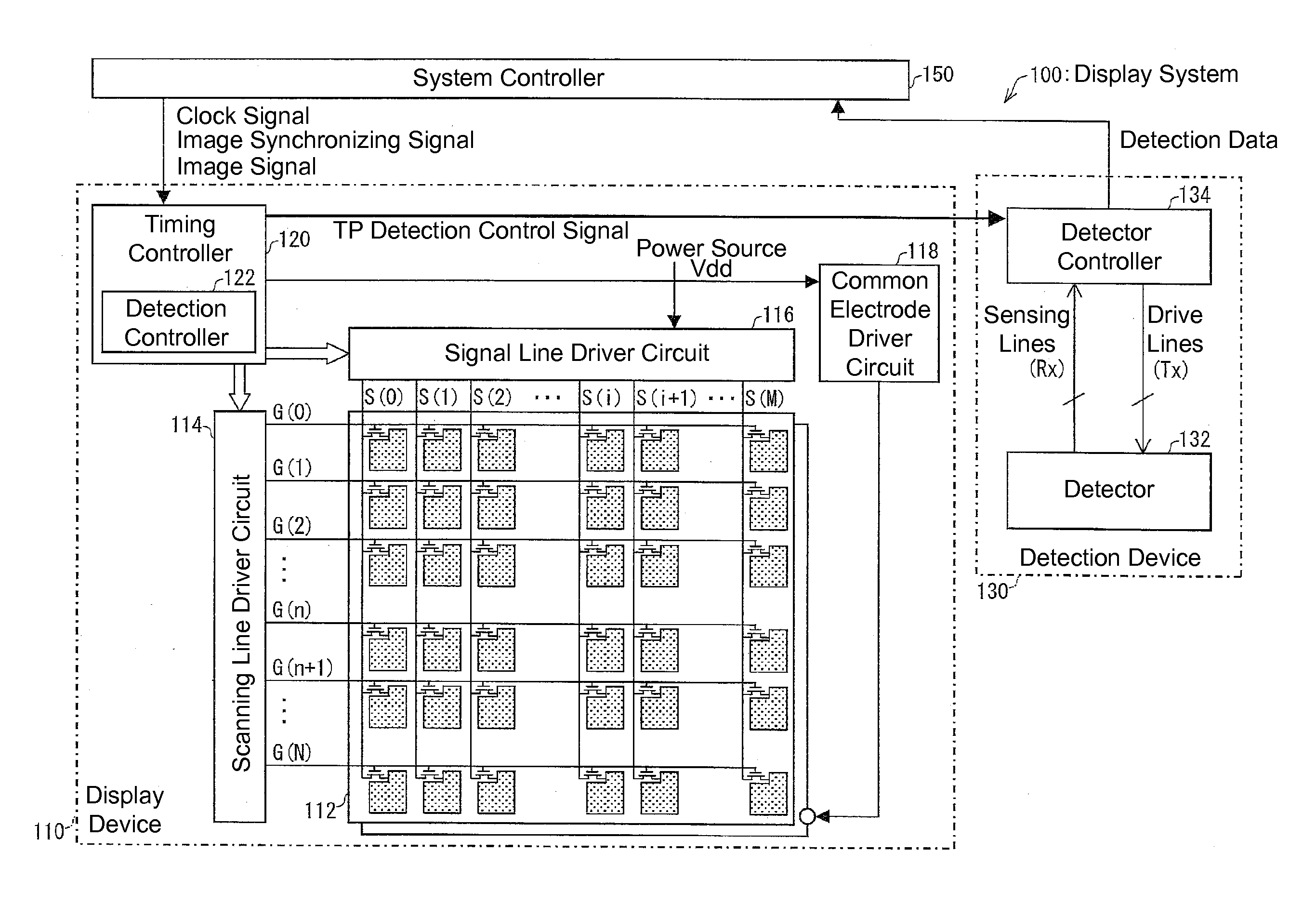
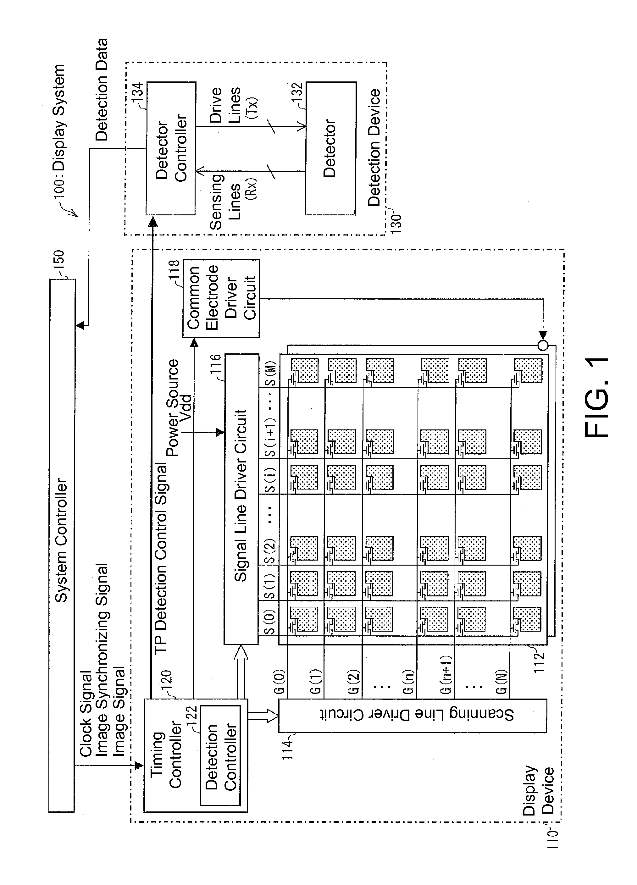
[0027]First, a configuration example of a display system 100 of Embodiment 1 will be described with reference to FIG. 1. FIG. 1 shows an overall configuration of the display system 100 of Embodiment 1.

[0028]As shown in FIG. 1, the display system 100 includes a display device 110, a detection device 130, and a system controller 150.

[0029]The display system 100 is included in mobile information devices (hereinafter referred to as the main device) such as mobile phones, smartphones, PDAs (personal digital assistants), and electronic books, for example, and has the function of inputting and displaying various data in the main device.

[0030]The detection device 130 is for inputting various data to the main device. The display device 110 is for displaying various data from the main device.

[0031]In the present embodiment, an active matrix liq...

Example

Embodiment 2

[0108]First, Embodiment 2 of the present invention will be explained with reference to FIG. 6.

[0109](Configuration of Display System)

[0110]FIG. 6 shows an overall configuration of the display system 100 of Embodiment 2.

[0111]As shown in FIG. 6, the display system 100 of Embodiment 2 differs from the display system 100 of Embodiment 1 in that a TP detection control signal outputted by a timing controller 120 is sent to a detector controller 134 through a system controller 150.

[0112]When the system controller 150 receives the TP detection control signal from the timing controller 120, it sends a TP detection control signal′ (the TP detection control signal in FIG. 6) based on this TP detection control signal to the detector controller 134. The TP detection control signal′ is a signal in a form readable by the detector controller 134.

[0113]In this manner, in the display system 100 of Embodiment 2, by sending the TP detection control signal′ to the detection device 130 throu...

Example

Embodiment 3

[0114]Next, Embodiment 3 of the present invention will be explained.

[0115]Material of Source Signal Line and Gate Signal Line

[0116]In Embodiment 3, each of a plurality of gate signal lines G and a plurality of source signal lines S included in a display panel 112 is made of copper, which has a lower wiring resistance than aluminum or the like.

[0117]As already explained in Formulae (3) and (4) and the like, as the wiring resistance Rs in the source signal lines S becomes greater, the delay period in the source signal lines S becomes longer. Also, as the wiring resistance Rg in the gate signal lines G becomes greater, the delay period in the gate signal lines G becomes longer.

[0118]In the display device 110 of Embodiment 3, it is possible to reduce the wiring resistance Rs of the source signal lines S by using copper in the source signal lines S, and thus, it is possible to shorten the delay period in the source signal line S based on the Formula (3). In other words, in th...


PUM


Abstract

A display device (110) is provided with a detection controller (122) that controls a detection device (130) such that detection is carried out within a horizontal blanking period for a display panel (112). An oxide semiconductor is used in the semiconductor layer for a TFT for each of the plurality of pixels provided in the display panel (112).

Description

TECHNICAL FIELD[0001]The present invention relates to a display device and display system.BACKGROUND ART[0002]Recently, display devices with a thin profile, light weight, and low power consumption such as liquid crystal display devices are widely used. Such display devices are mainly used for mobile phones, smartphones, PDAs (personal digital assistants), electronic books, laptop personal computers, and the like, for example. Also, electronic paper, which is an even thinner display device, is expected to be developed and put in practical use rapidly in the coming years.[0003]Among such display devices, touch panels are widely used as the input device for inputting various information. Generally, touch panels are provided so as to cover the surface of the display panel. Thus, touch panels are susceptible to receiving noise from the display panel, and a resulting issue is that the detection accuracy of the touch panel could not be improved sufficiently.[0004]Techniques that aim to sol...

Claims


Application Information

Patent Timeline
IPC IPC(8): H01L27/12G09G3/36G06F3/041
CPCH01L27/124G06F3/0412G09G3/3648H01L27/1225G09G2354/00G02F1/1368G02F1/13338G06F3/0446
Inventor SAITOH, KOHJIFUJIOKA, AKIZUMIOZAKI, MASAMIYANAGI, TOSHIHIRO
Owner SHARP KK
Why Eureka
Try Eureka