
Support assembly for a core drill

a core drill and support assembly technology, applied in the direction of tool workpiece connection, manufacturing tools, transportation and packaging, etc., can solve the problems of a certain amount of deflection associated with the use of the core drill, and achieve the effect of improving the structural support and improving the structure strength

Inactive Publication Date: 2014-11-13
WESTERN SAW MFR
View PDF2 Cites 11 Cited by
  • Summary
  • Abstract
  • Description
  • Claims
  • Application Information

AI Technical Summary

Benefits of technology

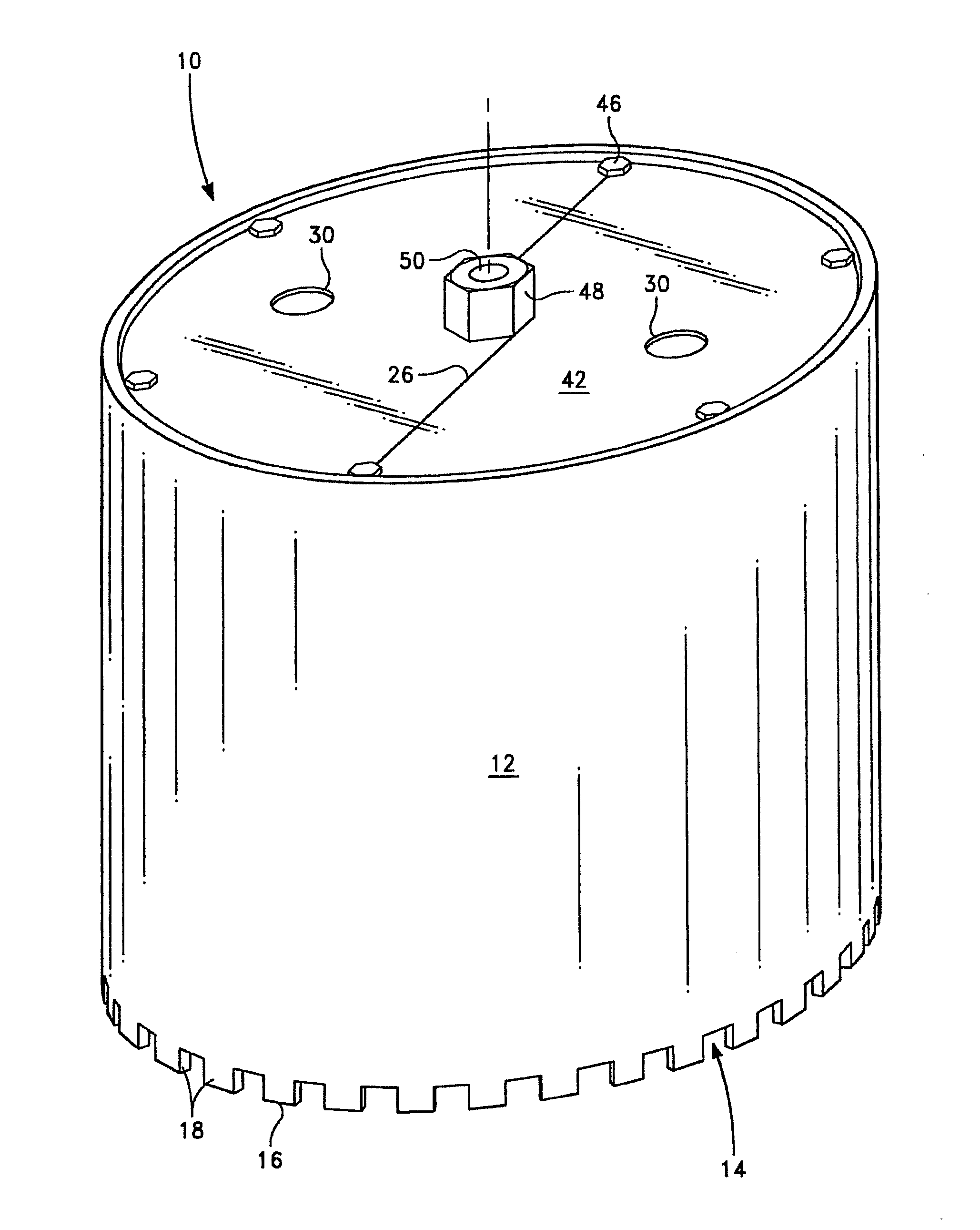
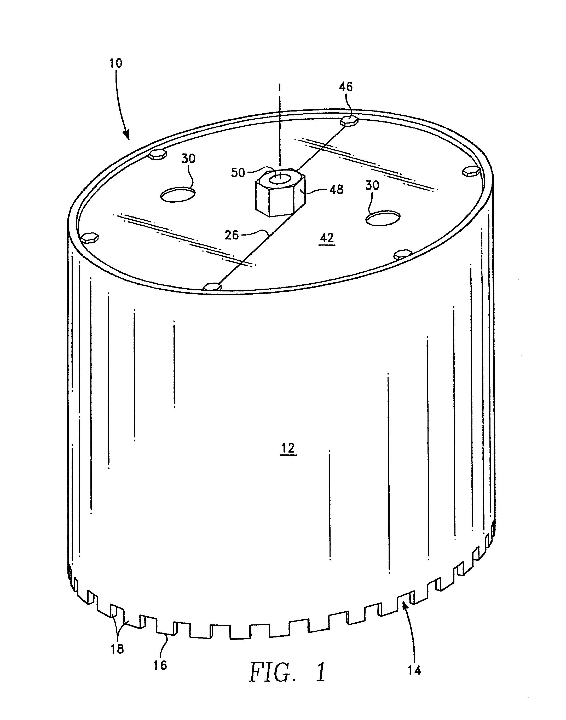
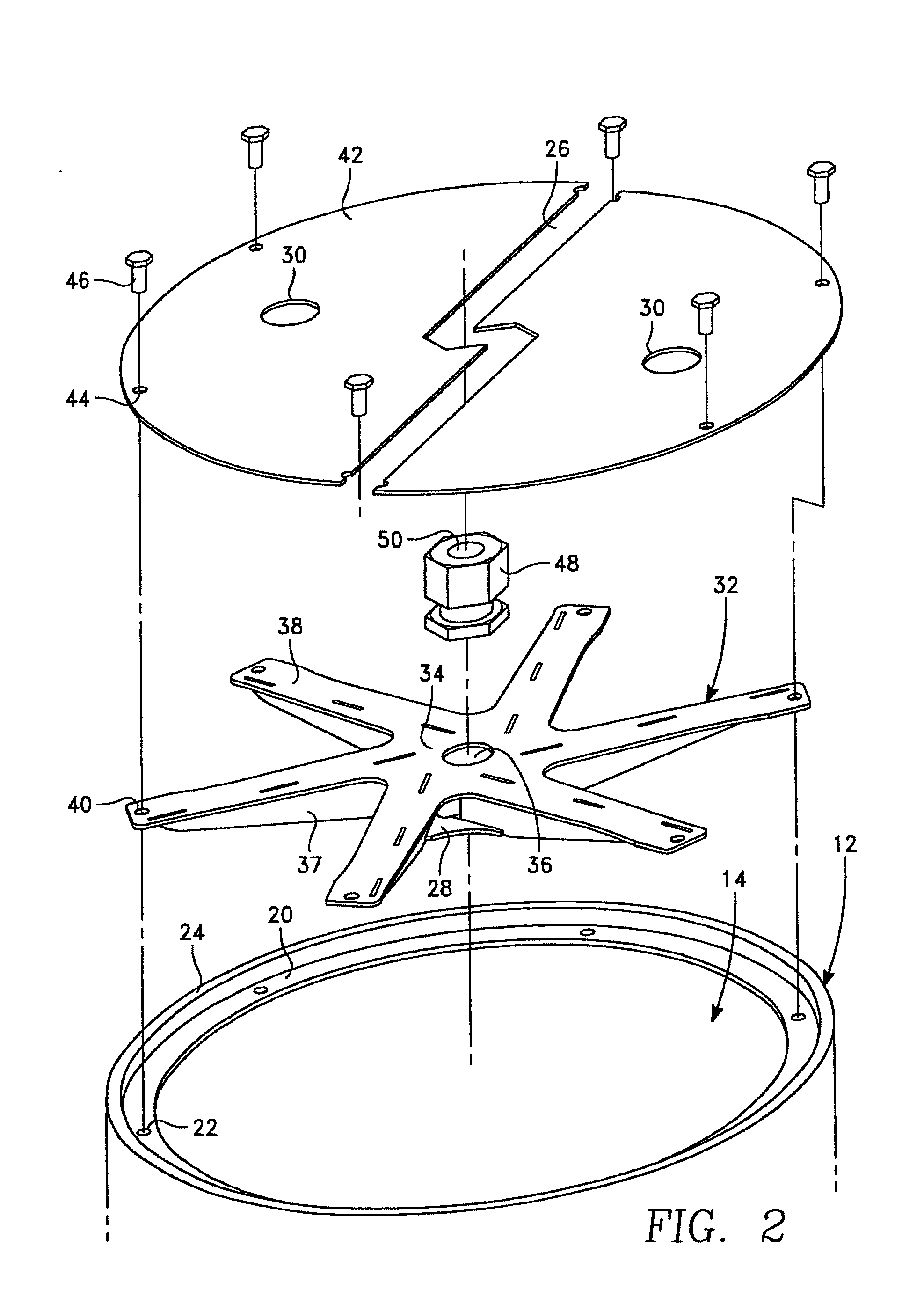
This patent describes a reinforcement system for a structure, such as a core drill, that includes a high strength spked reinforcer with a water stop disc to prevent water from passing through. The reinforcement can also be non-planar or have a non-planar component, such as a triangular-cross-section tubular or channel structure, which can be produced by extrusion, roll-formation, or machining. Slanted elements can also be used to improve structural support, which can be monolithic with a spoke, arm, or extension or combined with other elements in the X-Y or Z-axis directions. The patent provides various configurations and methods for creating a reinforcement system for a structure such as a core drill.

Problems solved by technology

Furthermore, there is a certain amount of deflection associated with the use of the core drill.

Method used


Image

  • Support assembly for a core drill
  • Support assembly for a core drill
  • Support assembly for a core drill

Examples


Embodiment Construction

[0065]This specification taken in conjunction with the drawings sets forth examples of apparatus and methods incorporating one or more aspects of the present inventions in such a manner that any person skilled in the art can make and use the inventions. The examples provide the best modes contemplated for carrying out the inventions, although it should be understood that various modifications can be accomplished within the parameters of the present inventions.

[0066]Various benefits will become more apparent with consideration of the description of the examples herein. However, it should be understood that not all of the benefits or features discussed with respect to a particular example must be incorporated into a tool, component or method in order to achieve one or more benefits contemplated by these examples. Additionally, it should be understood that features of the examples can be incorporated into a tool, component or method to achieve some measure of a given benefit even thoug...


PUM

PropertyMeasurementUnit
diameteraaaaaaaaaa
diameteraaaaaaaaaa
diameteraaaaaaaaaa

Abstract

A support assembly for a core drill which utilizes an improved high strength spoked reinforcer. The reinforcer may be removably mounted a core drill tube by fasteners. A drive connection is removably mounted and centrally located on an outer disc of a pair of discs. The drive connection is adapted to connect with a drive shaft to cause rotation of the tube. The assembly can also include a split in the disc when the high strength spoked reinforcer is not welded thereto, thereby providing a means of water control. The high strength spoked reinforcer can be a separate piece that is bolted to the disc or can be integrally formed as one piece therewith.

Description

CROSS REFERENCE TO RELATED APPLICATIONS[0001]This application is a continuation-in-part of U.S. Ser. No. 12 / 799,615, filed Apr. 27, 2010, published as US 2011 / 0262237, now U.S. Pat. No. 8,790,052, issued Jul. 29, 2014; and a continuation-in-part of PCT / US11 / 00748, filed Apr. 26, 2011, and US National Stage application Ser. No. 14 / 114,510, filed Jan. 7, 2014, published as US 2014 / 0112728, the entire content and disclosures of which are incorporated herein fully by reference.BACKGROUND[0002]1. Field[0003]The field of this invention relates generally toward cutting implements and more particularly to the construction of a core drill.[0004]2. Related Art[0005]Core drills are commonly used for drilling holes in hard materials, such as concrete and masonry. These holes are then used to support a structural member, such as a post, which is used on a support member for a building structure or for forming a large diameter borehole with the borehole being used for the passage of pipe lines or...

Claims


Application Information

Patent Timeline
Patent Type & Authority Applications(United States)
IPC IPC(8): B23B51/04
CPCB23B51/0473B23B51/0406B23B2251/248B23B2251/428B23B2250/12B27B5/30B28D1/041B23B2226/75B23B2240/16Y10T408/895
Inventor BARATTA, ANTHONY
Owner WESTERN SAW MFR
Learn More