
Temperature Control Method in a Laboratory Scale Reactor

Inactive Publication Date: 2014-11-13
CLEAN DIESEL TECHNOLOGIES
View PDF2 Cites 17 Cited by
  • Summary
  • Abstract
  • Description
  • Claims
  • Application Information

AI Technical Summary

Benefits of technology

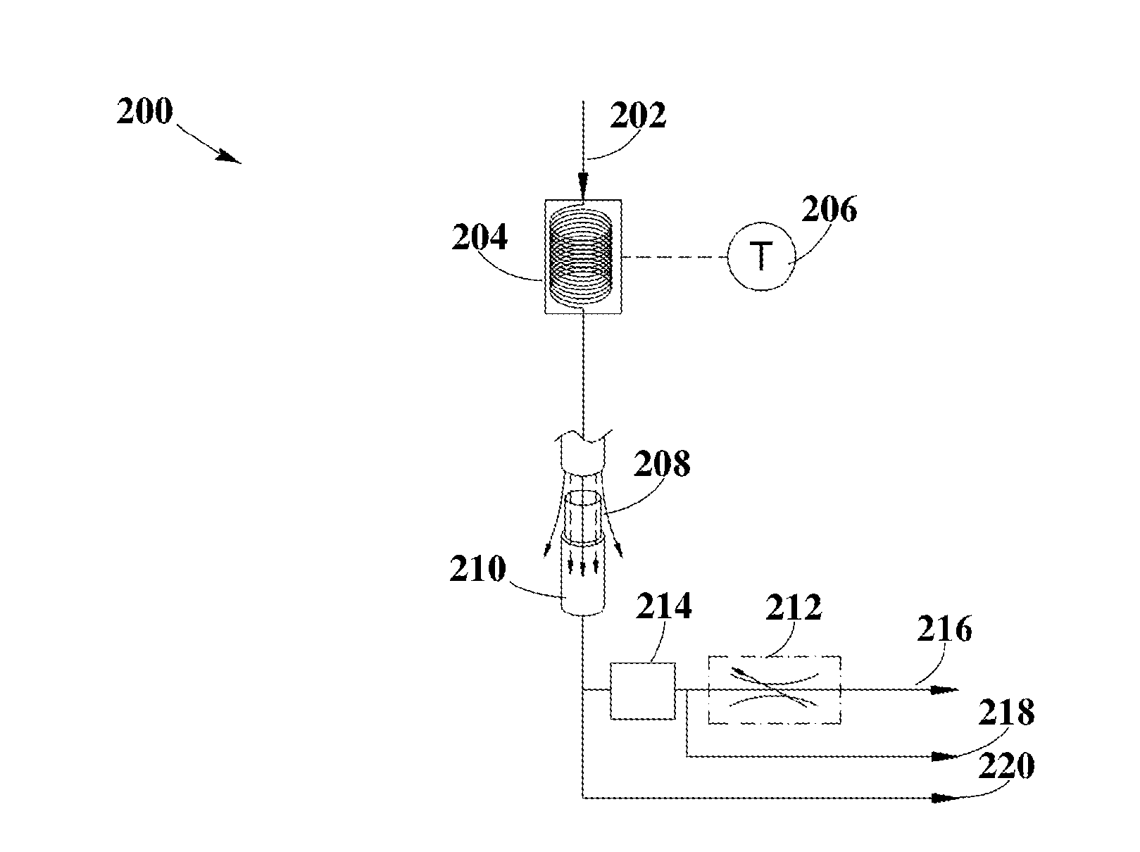
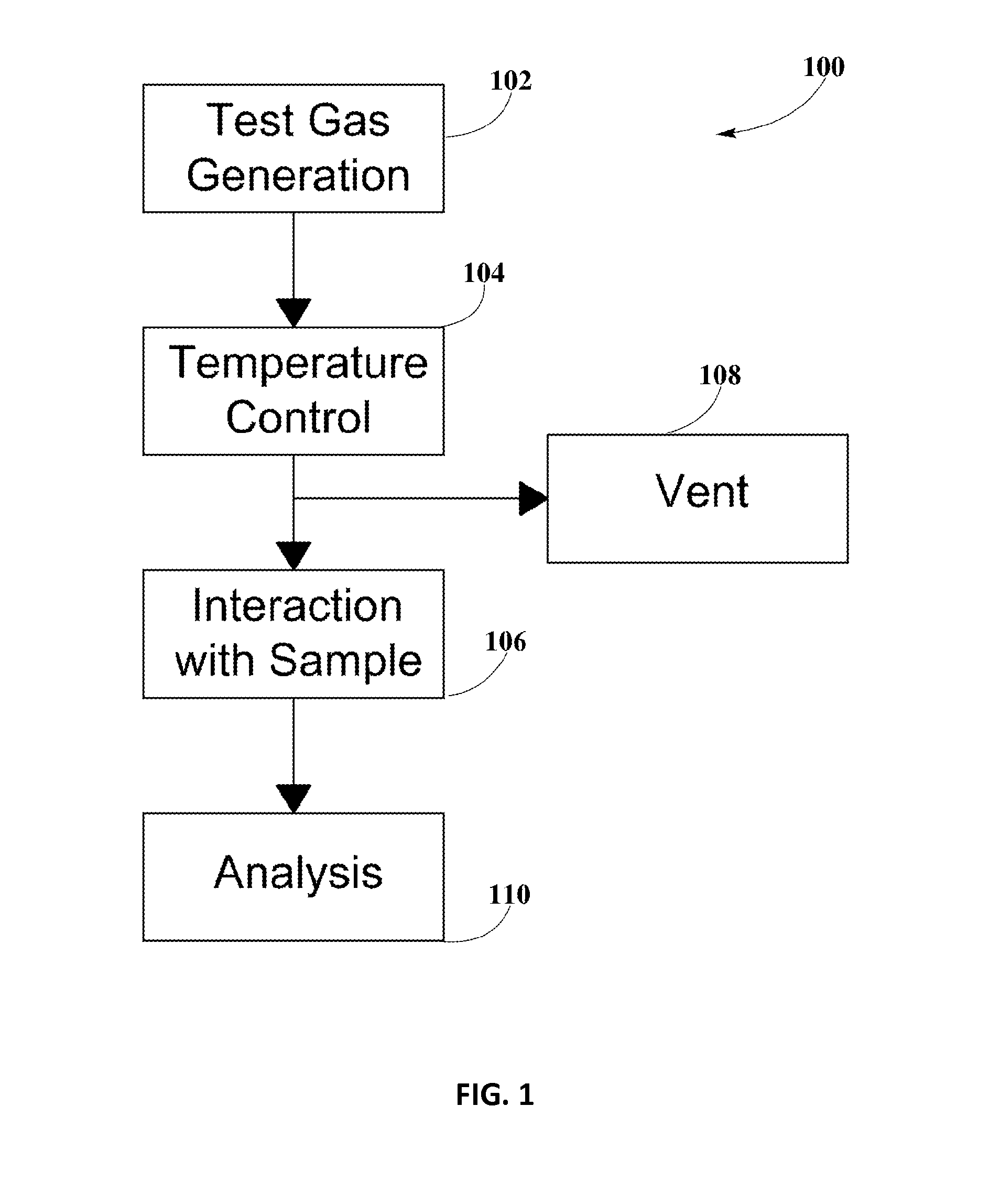
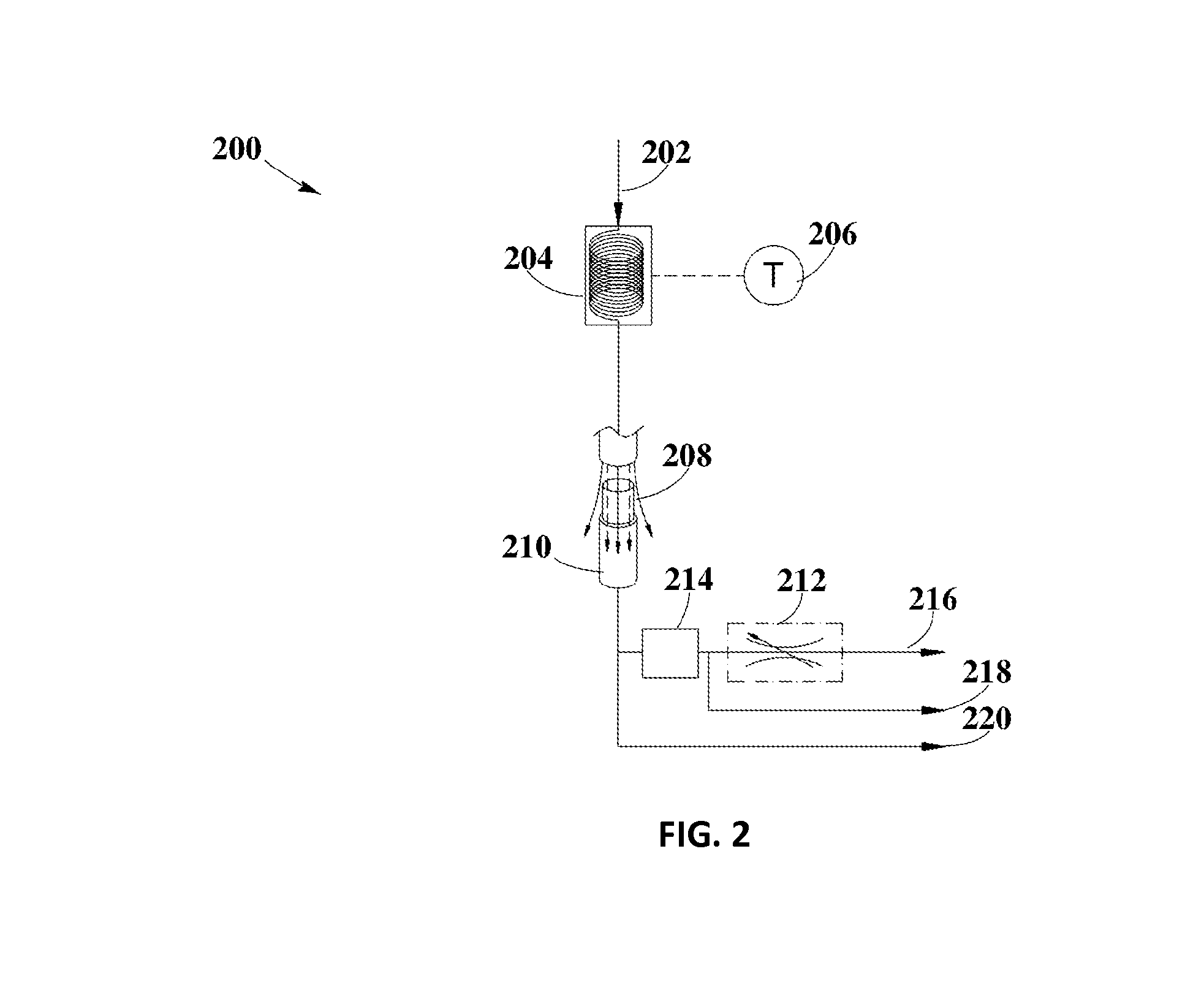
The patent text describes a method for testing a catalyst by heating it and measuring the gas flow through it. The method separates the heating from the gas flow, so that the space-velocity of the gas can change independently from the heating. This allows for more accurate measurements of the catalyst's performance.

Problems solved by technology

Devices of use in testing catalysts may include one or more combustion engines; however, the use of these engines may be expensive, require higher maintenance than desired, and be more time consuming.
Additionally, the use of these engines may not allow individual parameter variations or calibrations of use when testing catalysts.
However, Laboratory-scale reactors may experience difficulties in separating control of one or more individual parameters or calibrations, including the separation of control of mass flow through the sample from temperature control of the gas flowing through the sample.
This may limit the conditions laboratory scale reactors may produce for testing suitable materials.

Method used


Image

  • Temperature Control Method in a Laboratory Scale Reactor
  • Temperature Control Method in a Laboratory Scale Reactor
  • Temperature Control Method in a Laboratory Scale Reactor

Examples


Embodiment Construction

Definitions

[0015]As used here, the following terms have the following definitions:

[0016]Mass flow controller (MFC) refers to any computer controlled analog or digital device of use in controlling the flow rate of fluids and / or gases.

[0017]Temperature controller refers to any device of use in controlling temperature in a process.

[0018]Laboratory Scale Reactor / Test Bench refers to any apparatus suitable for testing a material with a test gas.

[0019]Oxidizing agent refers to any substance that may take electrons from another substance in a redox chemical reaction.

[0020]Reducing agents refers to any substance that may give electrons to another substance in a redox chemical reaction.

[0021]Gas mixture refers to the mixture obtained from combining oxidizing agents, reducing agents, inert gases, or any other suitable gases.

[0022]Water-gas mixture refers to the mixture obtained from combining water vapor with a gas mixture.

[0023]Test Gas refers to any gas mixture of use in chemically testing ...


PUM


Abstract

Disclosed herein is a method of separating variations in the mass flow of gas through a catalyst from the thermal load observed by the temperature control system in a test bench. The method may include separating the temperature control component from the mass flow control component.

Description

CROSS-REFERENCE TO RELATED APPLICATIONS[0001]N / ABACKGROUND [0002]1. Field of the Disclosure[0003]The present disclosure relates to a laboratory test device and, more particularly, to a method for controlling test gas temperatures in a test bench.[0004]2. Background Information[0005]Catalysts may need to be tested to evaluate their performance and their response to parameter changes. Devices of use in testing catalysts may include one or more combustion engines; however, the use of these engines may be expensive, require higher maintenance than desired, and be more time consuming. Additionally, the use of these engines may not allow individual parameter variations or calibrations of use when testing catalysts. Other test devices suitable for testing catalysts may include Laboratory Scale Reactors, commonly referred to as Test Benches, and may allow a greater control over the testing conditions of the catalyst.[0006]However, Laboratory-scale reactors may experience difficulties in sep...

Claims


Application Information

Patent Timeline
IPC IPC(8): G01N33/00
CPCG01N33/0016G01N33/0037G01N33/004Y02A50/20
Inventor HATFIELD, RANDAL L.
Owner CLEAN DIESEL TECHNOLOGIES
Learn More