Pressure feed container, storage method using the pressure feed container, and method for transferring liquid using the pressure feed container

a technology of pressure feed and container, which is applied in the direction of containers, transportation and packaging, containers preventing decay, etc., can solve the problems of increasing the damage of wafers, reducing the size of particles that reduce the manufacturing yield, and reducing the cleanliness of liquids. , to achieve the effect of suppressing the electrostatic charge in the liquid and ensuring the cleanliness of liquids

Inactive Publication Date: 2014-11-20
CENT GLASS CO LTD
View PDF11 Cites 6 Cited by
  • Summary
  • Abstract
  • Description
  • Claims
  • Application Information

AI Technical Summary

Benefits of technology

[0057]The pressure feed container of the present invention can ensure the cleanliness of a liquid such as a protective film-forming liquid chemical or a protective film-forming liquid chemical kit for preparing the liquid chemical even after long-term storage, and can also suppress electrostatic charge in the liquid.

Problems solved by technology

Consequently, the circuit patterns are becoming smaller, and the size of particles that reduce the manufacturing yield is also becoming smaller.
On the other hand, there is a problem arising from cleaning as conventionally performed with an ammonia-mixed cleaning agent.
That is, as the circuit patterns become smaller, more damage is caused to the wafer due to the basicity of such an agent.
The alternative has alleviated damage to the wafer caused by cleaning; however, problems due to a higher aspect ratio associated with smaller semiconductor devices have become obvious.
In other words, a phenomenon where a pattern collapses when a gas-liquid interface passes through the pattern occurs after cleaning or rinsing, significantly reducing the yield.
This phenomenon has been a serious problem.

Method used


Image

  • Pressure feed container, storage method using the pressure feed container, and method for transferring liquid using the pressure feed container
  • Pressure feed container, storage method using the pressure feed container, and method for transferring liquid using the pressure feed container
  • Pressure feed container, storage method using the pressure feed container, and method for transferring liquid using the pressure feed container

Examples


example 1

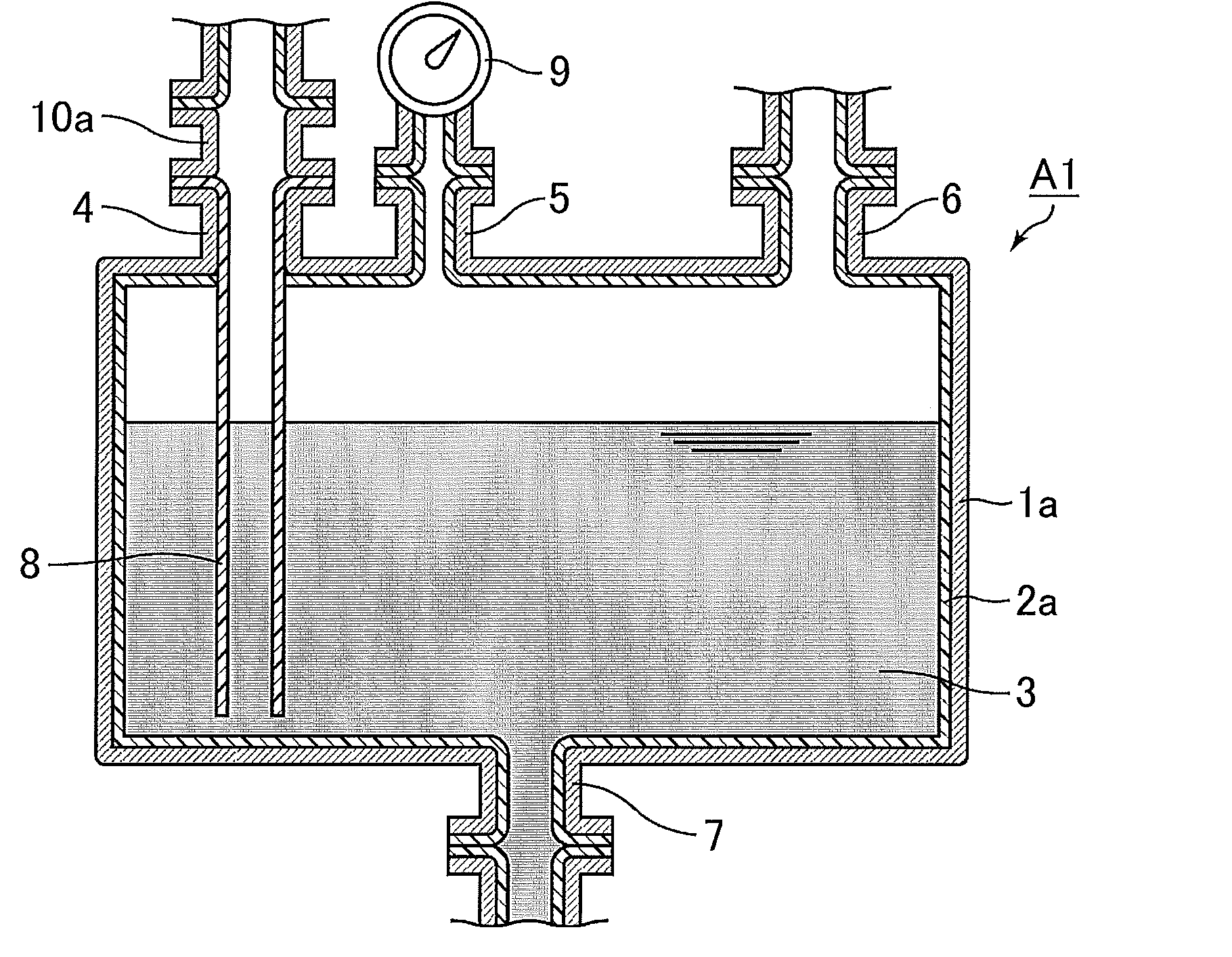
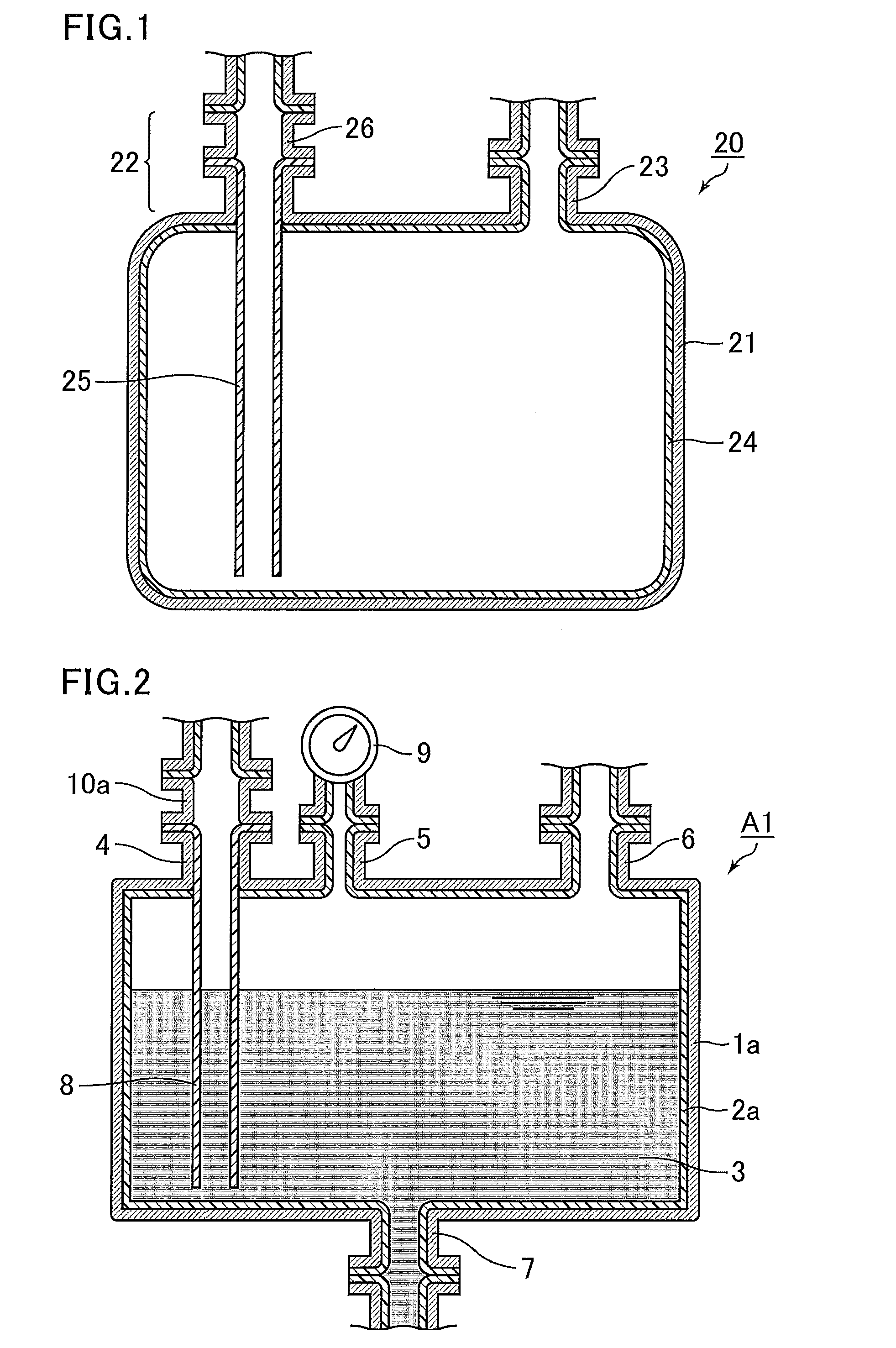
[0172]In this example, a pressure feed container A1 shown in FIG. 2 was used. The container Al includes a container body 1a, nozzles 4, 5, 6, and 7, and a neutralization mechanism 10a configured to reduce electrostatic potential. The nozzles 4, 5, 6, and 7 and the neutralization mechanism 10a are formed from SUS304. The container body 1a includes a SUS304 metal can body and a PFA lining layer 2a covering the inner surface of the metal can body. The inner surfaces of the container body 1a and the nozzles 4, 5, 6, and 7, which are configured to contact a sample liquid, are covered with the PFA lining layer 2a. The nozzle 4 is connected with a PFA liquid-introducing and -extracting nozzle 8. The nozzle 5 is connected with a bellows manometer 9 whose liquid contact portion is formed from PFA. The nozzles 4, 6, and 7 are each connected with a valve, a coupler, or the like (not shown). Such connection of the aforementioned components keeps the container airtight. The surfaces configured t...

example 2

[0176]The same operations were performed as in Example 1 except that the metal can body of the container body 1a and the neutralization mechanism 10a formed from electropolished SUS316L were used. Table 1 shows the evaluation conditions and Table 2 shows the evaluation results.

example 3

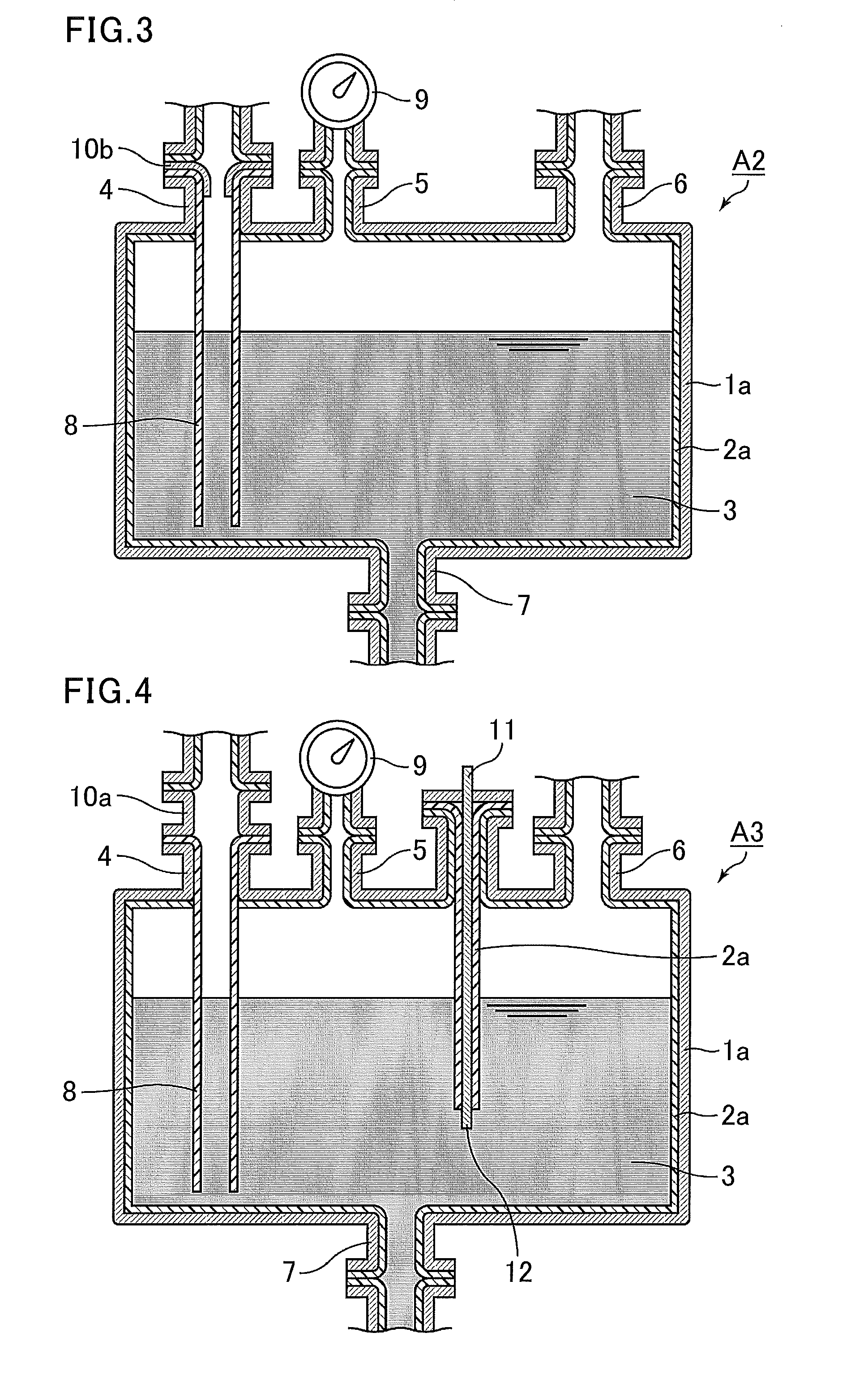
[0177]In this example, a pressure feed container A2 shown in FIG. 3 was used. The container A2 includes, as a neutralization mechanism 10b, a SUS304 sleeve member (inner diameter: 28.4 mφ, length: 10 mm, liquid contact area: 8.9 cm2) incorporated with the nozzle 4, and the sleeve member is configured to contact a sample liquid. The neutralization mechanism 10b (sleeve member) is grounded via a wire or the like (not shown). The portions (e.g. the wire for grounding) excluding the liquid contact portion of the neutralization mechanism 10b do not contact a sample liquid. Except for the above, the container A2 has a structure similar to that of the pressure feed container A1 shown in FIG. 2. The same operations were performed as in Example 1 except that the above pressure feed container A2 was used. Table 1 shows the evaluation conditions and Table 2 shows the evaluation results.


PUM


Abstract

The present invention provides a pressure feed container capable of ensuring the cleanliness of a liquid such as a protective film-forming liquid chemical or a protective film-forming liquid chemical kit for preparing the liquid chemical even after long-term storage, and also capable of suppressing electrostatic charge in the liquid. The present invention provides a pressure feed container configured to store a protective film-forming liquid chemical or a protective film-forming liquid chemical kit that is mixed into the protective film-forming liquid chemical, and to transfer a liquid upon application of pressure to the inside of the container, the protective film-forming liquid chemical being for forming a water-repellent protective film on at least surfaces of recessed portions of an uneven pattern formed on a surface of a wafer containing a silicon element at least at a part of the uneven pattern. The protective film-forming liquid chemical contains a nonaqueous organic solvent, a silylation agent, and an acid or a base; the protective film-forming liquid chemical kit includes a treatment liquid A containing a nonaqueous organic solvent and a silylation agent, and a treatment liquid B containing a nonaqueous organic solvent and an acid or a base; the pressure feed container includes a container body configured to contain a liquid selected from the protective film-forming liquid chemical, the treatment liquid A, and the treatment liquid B, and a liquid flowing nozzle configured such that the liquid flows therethrough to be introduced into the container body and/or to be extracted from the container body; the container body includes a metal can body in which a portion configured to contact the liquid is formed from a resin material; the liquid flowing nozzle is provided with a neutralization mechanism configured to reduce electrostatic potential in the liquid; and a liquid contact portion of the liquid flowing nozzle excluding the neutralization mechanism is formed from a resin material.

Description

TECHNICAL FIELD[0001]The present invention relates to a pressure feed container, a storage method using the pressure feed container, and a method for transferring a liquid using the pressure feed container. More specifically, the present invention relates to a pressure feed container configured to store a water-repellent protective film-forming liquid chemical or a water-repellent protective film-forming liquid chemical kit for improving a cleaning step in the manufacture of semiconductor devices or the like. The cleaning step tends to cause collapse of an uneven pattern formed on the surface of a wafer containing a silicon element at least at a part of the uneven pattern.BACKGROUND ART[0002]Semiconductor devices for use in electrical communication networks and digital household electric appliances are required to have higher performance, higher functionality, and lower power consumption. Consequently, the circuit patterns are becoming smaller, and the size of particles that reduce ...

Claims


Application Information

Patent Timeline
Patent Type & Authority Applications(United States)
IPC IPC(8): B05B9/04B65B31/00
CPCB65B31/00B05B9/04H01L21/67017H01L21/02057B65D81/24B65D25/14B65D25/40
Inventor RYOKAWA, ATSUSHIYAMADA, SHUHEIFUJITANI, MASAHIROHASHIMOTO, YOSUKEIDETA, CHIAKIKUMON, SOICHISAITO, MASANORISAIO, TAKASHI
Owner CENT GLASS CO LTD
Why Eureka
Try Eureka