Metrology system calibration refinement

a technology of metalrology and calibration refinement, applied in the direction of optical radiation measurement, optically investigating flaws/contaminations, instruments, etc., can solve the problems of loss of consistency among processed semiconductor wafers, difficulty in characterization, and increased computational burden, so as to reduce computational resources and reduce computational burden

Active Publication Date: 2014-11-20
KLA TENCOR TECH CORP
View PDF13 Cites 35 Cited by
  • Summary
  • Abstract
  • Description
  • Claims
  • Application Information

AI Technical Summary

Benefits of technology

[0014]In yet another aspect, methods and systems to perform parameter tuning based on a low-order response surface based optimization are presented. A low-order response surface based optimization reduces the computational burden associated with selecting optimal system parameter values for one or more metrology tools. It is assumed that the response of performance metrics to variations of system parameter values is reasonably approximated by low order polynomials. The low-order response surfaces are constructed using a small number of model evaluations. This significantly reduces the computational resources required to arrive at a refined set of system calibration parameters.

Problems solved by technology

As devices (e.g., logic and memory devices) move toward smaller nanometer-scale dimensions, characterization becomes more difficult.
Devices incorporating complex three-dimensional geometry and materials with diverse physical properties contribute to characterization difficulty.
If measurement consistency degrades in a manufacturing environment, consistency among processed semiconductor wafers is lost and yield drops to unacceptable levels.
However, the accuracy of a metrology system calibrated based on reference wafers is typically limited to wafers with properties that closely match those of the reference wafer.
Thus, the effectiveness of calibration based on thin film measurements may be limited in different measurement applications.
This may be difficult to achieve in a manufacturing environment and lead to loss of consistency among metrology systems.
In addition, an expensive reference wafer set must be maintained in the manufacturing environment.
Risks of wafer breakage or degradation potentially jeopardize the integrity of the calibration process.
Tool-to-tool matching and maintaining tool measurement consistency over time, over maintenance cycles, and over a wide range of measurement applications are core challenges in the development of an optical metrology system that meets customer requirements of the semi-conductor industry.
Furthermore, the spectral error associated with the measurement by the target metrology system is determined based at least in part on a parameter of the specimen that is accurately measured by the second measurement subsystem.
This significantly reduces the computational resources required to arrive at a refined set of system calibration parameters.

Method used


Image

  • Metrology system calibration refinement
  • Metrology system calibration refinement
  • Metrology system calibration refinement

Examples


Embodiment Construction

[0035]Reference will now be made in detail to background examples and some embodiments of the invention, examples of which are illustrated in the accompanying drawings.

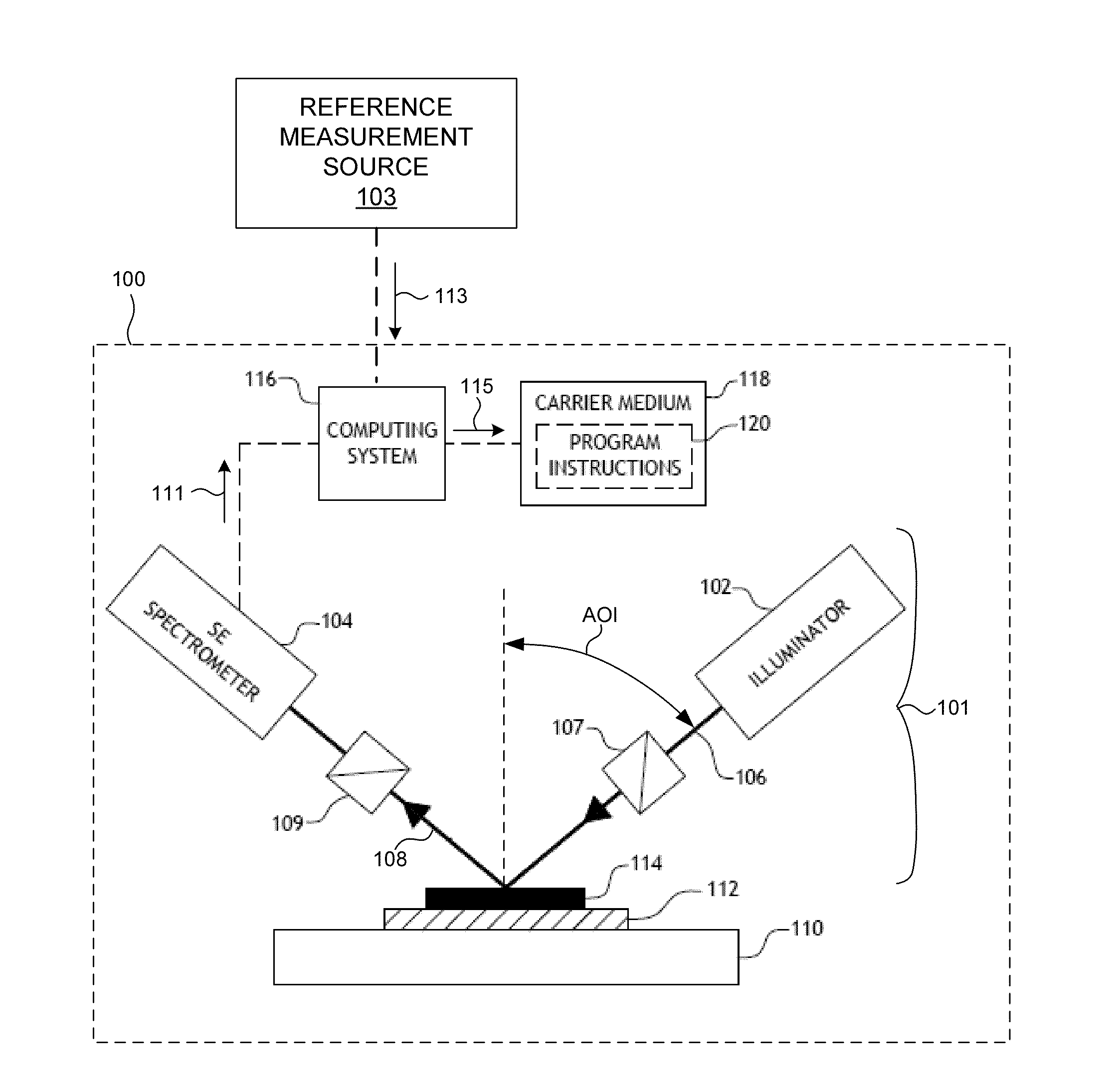
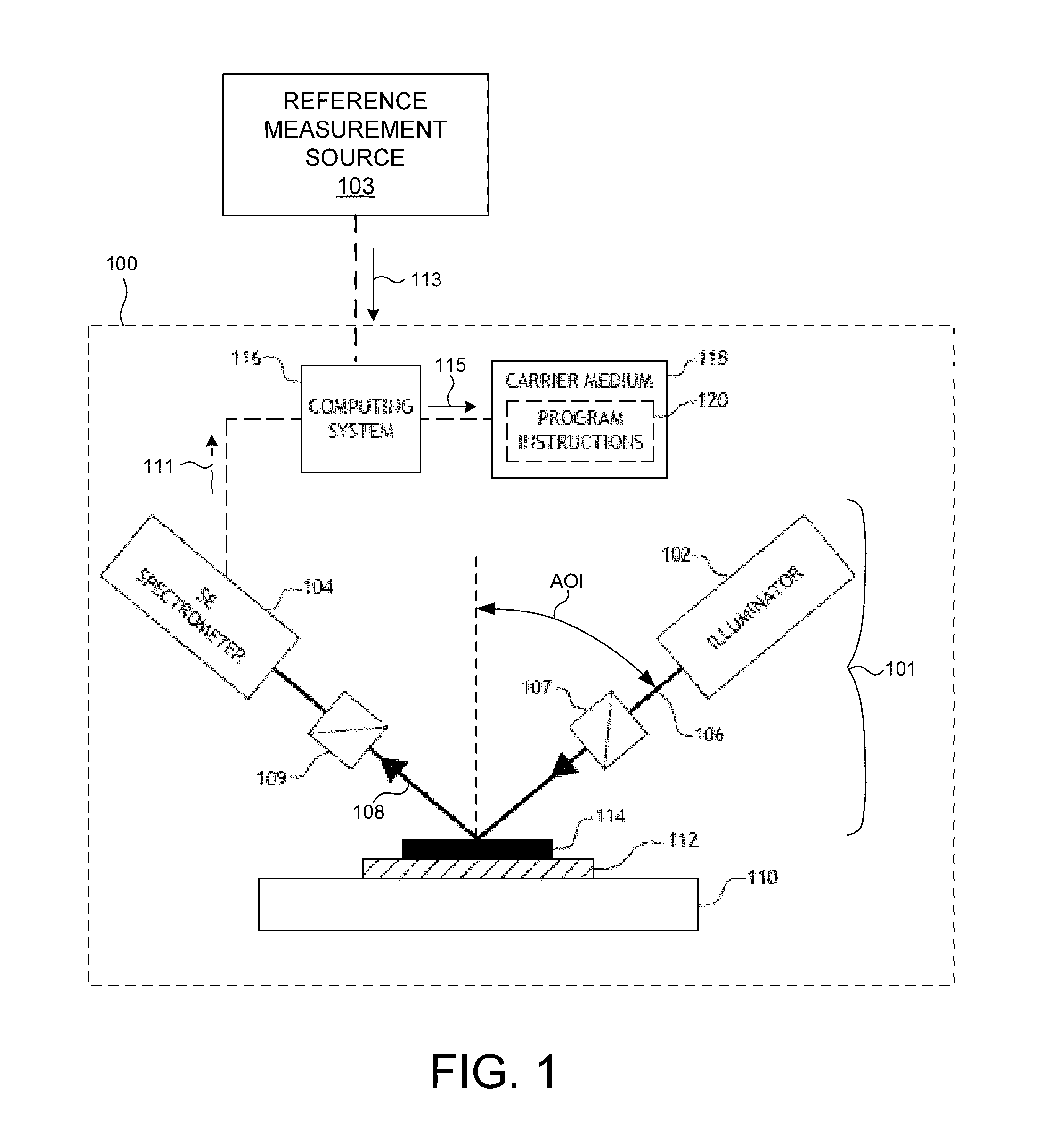
[0036]FIG. 1 illustrates a metrology system 100 for measuring characteristics of a semiconductor wafer in accordance with the exemplary methods presented herein. As shown in FIG. 1, the system 100 may be used to perform spectroscopic ellipsometry measurements of one or more structures 114 of a semiconductor wafer 112 disposed on a wafer positioning system 110. In this aspect, the system 100 may include a spectroscopic ellipsometer (SE) 101 equipped with an illuminator 102 and a spectrometer 104. The illuminator 102 of the system 100 is configured to generate and direct illumination of a selected wavelength range (e.g., 150-850 nm, 190-850 nm, 240-850 nm, etc.) to the structure 114 disposed on the surface of the semiconductor wafer 112. In turn, the spectrometer 104 is configured to receive illumination reflected from ...


PUM

PropertyMeasurementUnit
wavelengthsaaaaaaaaaa
wavelength rangeaaaaaaaaaa

Abstract

Methods and systems for matching measurement spectra across one or more optical metrology systems are presented. The values of one or more system parameters used to determine the spectral response of a specimen to a measurement performed by a target metrology system are optimized. The system parameter values are optimized such that differences between measurement spectra generated by a reference system and the target system are minimized for measurements of the same metrology targets. Methods and systems for matching spectral errors across one or more optical metrology systems are also presented. A trusted metrology system measures the value of at least one specimen parameter to minimize model errors introduced by differing measurement conditions present at the time of measurement by the reference and target metrology systems. Methods and systems for parameter optimization based on low-order response surfaces are presented to reduce the compute time required to refine system calibration parameters.

Description

CROSS REFERENCE TO RELATED APPLICATION[0001]The present application for patent claims priority under 35 U.S.C. §119 from U.S. provisional patent application Ser. No. 61 / 827,536, entitled “Spectral Calibration Refinement (SCR) for CD Matching Improvement,” filed May 24, 2013, U.S. provisional patent application Ser. No. 61 / 824,363, entitled “Spectral Error Matching Based Calibration with Reference Measurement,” filed May 16, 2013, and U.S. provisional patent application Ser. No. 61 / 838,236, entitled “Response Surface Approach to Application-Specific Calibration Refinement For Metrology Devices,” filed Jun. 22, 2013. The subject matter of each is incorporated herein by reference in their entireties.TECHNICAL FIELD[0002]The described embodiments relate to systems for wafer metrology, and more particularly to characterization and defect detection of semiconductor structures and materials.BACKGROUND INFORMATION[0003]Semiconductor devices such as logic and memory devices are typically fab...

Claims


Application Information

Patent Timeline
Patent Type & Authority Applications(United States)
IPC IPC(8): G01N21/21G01N21/95
CPCG01N21/211G01N2021/213G01N21/9501G01B2210/56G01N21/274
Inventor KWAK, HIDONGLESOINE, JOHNSADIQ, MALIKWEI, LANHUAKRISHNAN, SHANKARPOSLAVSKY, LEONIDSUSHCHIK, MIKHAIL M.
Owner KLA TENCOR TECH CORP
Why Eureka
Try Eureka