
Laser and phosphor based light source for improved safety

a technology of phosphor and light source, applied in the field of light source, can solve the problems of low emission efficiency of conventional devices in which a single colour led is used to eliminate a plurality of fluorescent materials, high luminance light source, and high light source restriction of laser light sour

Inactive Publication Date: 2014-11-20
SHARP KK
View PDF0 Cites 21 Cited by
  • Summary
  • Abstract
  • Description
  • Claims
  • Application Information

AI Technical Summary

Benefits of technology

The invention described in this patent has certain features that are beneficial in its use. These features, however, only represent a small portion of the various ways in which the principles of the invention can be employed. The patent aims to protect these features and the uses of the invention. Other objects and advantages of the invention can be inferred from the following description.

Problems solved by technology

The emission from a laser light source is highly restricted in terms of angular distribution and spatial extent, leading to a very high luminance light source.
It addresses the problem that conventional devices in which a single colour LED is used to eliminate a plurality of fluorescent materials has a low emission efficiency.

Method used


Image

  • Laser and phosphor based light source for improved safety
  • Laser and phosphor based light source for improved safety
  • Laser and phosphor based light source for improved safety

Examples


first embodiment

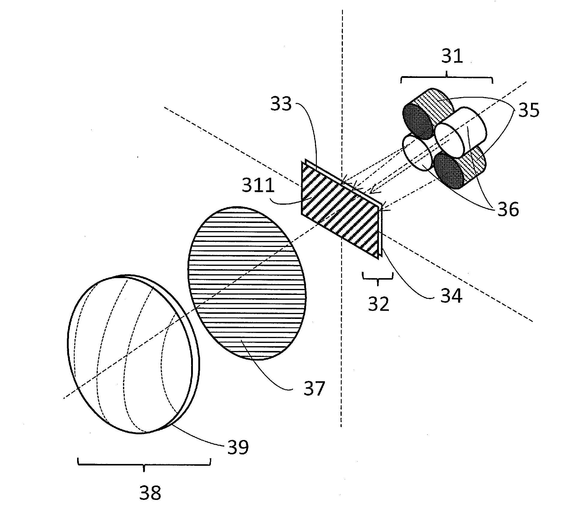
[0065]FIG. 6 illustrates a further embodiment of the present invention whereby the ratio of the mixture of phosphors is different to the For this reason the fluorescent material 41 on deposited on the substrate 34 in the light source 32 in FIG. 6 is denoted by a different numeral (41). The fluorescent material 41 is made from a mixture of phosphors in which the UV absorbing phosphor is formed solely from a phosphor (or phosphor mixture) which emits light in the blue waveband. The mixture of blue absorbing phosphors is created as in the main embodiment. The resultant mixture of both types of phosphor emits wavebands of different colours that when combined form a colour perceived as white. However, in this embodiment the vast majority of the light in the blue waveband forming the light perceived as white is formed from the emission from the UV absorbing phosphor which emits in the blue waveband, not the emission from the blue laser emitters which emit light in the blue waveband 36. A...

second embodiment

[0142]41. fluorescent material of the second embodiment

[0143]51. focal point

[0144]52. UV absorbing phosphor

[0145]53. blue absorbing phosphor

[0146]54. boundary between different phosphor mixtures

[0147]55. boundary region

[0148]61. raised central section

[0149]62. outer section

[0150]63. set back distance

[0151]64. discontinuity in the substrate

[0152]72. elliptical reflector

[0153]73. first focal point

[0154]74. optical axis

[0155]75. surface of the light source

[0156]76. light

[0157]77. second focal point

[0158]78. reflector vertex

[0159]101. projection type automotive headlight

[0160]102. aperture

[0161]103. light shield

[0162]111. headlight

[0163]112. vehicle

[0164]113. beam spot

[0165]114. road

[0166]115. oncoming vehicle

[0167]116. central control unit

[0168]117. driver console

[0169]118. automated input unit


PUM


Abstract

A light source system comprising an optical system which is arranged to project light from a light source into the far-field. The light source comprises a mixture of fluorescent materials which are sensitive to one of two wavebands in either the UV or blue part of the spectrum. The combination of the light emitted from both sets of fluorescent materials combined such that the resulting colour is perceived as white. The light source is illuminated by a plurality of laser emitters comprised of both emitters (35) in the UV waveband and emitters (36) in the blue waveband. The resultant light emitted has an improved eye safety by the reduction of laser light content.

Description

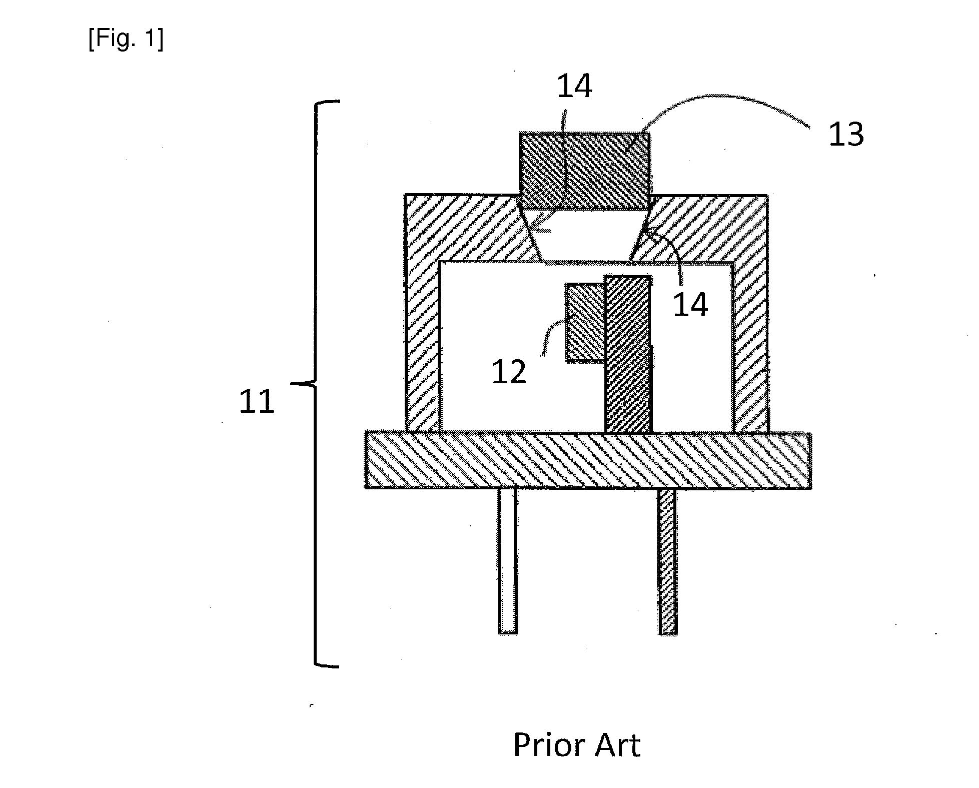
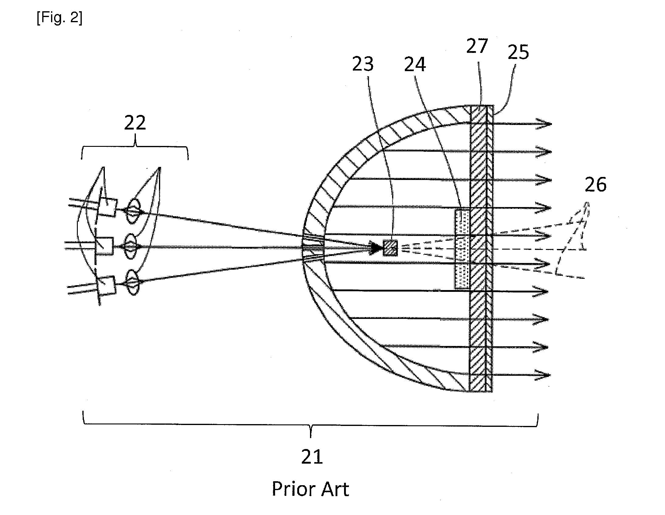
TECHNICAL FIELD[0001]The present invention relates to a light source for general lighting in which the laser safety of the emitted light must be considered for use in areas where extended exposure of humans to the light is possible.BACKGROUND ART[0002]The application of light sources to general lighting is well known. The development of light sources has led to sources with ever increasing luminance, in that there is an increasing output from of light from a decreasing area into a decreasing angular distribution. This has led to development of light sources such as high intensity discharge (HID) lamps based upon noble gases such as Xenon, or light emitting diodes (LED) based upon a semiconductor blue light emitting chip and a phosphor for wavelength conversion from blue to yellow light and the combination of the two wavebands to form white light. Both of these light sources are well known and will not be described further.[0003]Laser based light sources have been developed that offe...

Claims


Application Information

Patent Timeline
Patent Type & Authority Applications(United States)
IPC IPC(8): F21V9/16F21S8/10F21V9/08
CPCF21V9/16F21V9/08F21Y2101/025F21Y2101/02F21S48/1225F21S41/12F21S41/16F21V9/30F21S41/176H01S5/0087H01S5/32341H01S5/4025C09K11/70H01L33/504H01S5/02253
Inventor SUCKLING, JAMES ROWLANDMONTGOMERY, DAVID JAMESTAKAHASHI, KOJI
Owner SHARP KK
Learn More