Composite molded lens and method for producing the same
a technology lens barrels, which is applied in the field of composite molded lenses, can solve the problems of difficult to form a positioning or alignment face, difficult to align the position of the molded lens in the lens frame or the lens barrel, and improve the accuracy of centering the molded lens, so as to achieve excellent bonding performance between the lens body and the lens fram
- Summary
- Abstract
- Description
- Claims
- Application Information
AI Technical Summary
Benefits of technology
Problems solved by technology
Method used
Image

Examples
first embodiment
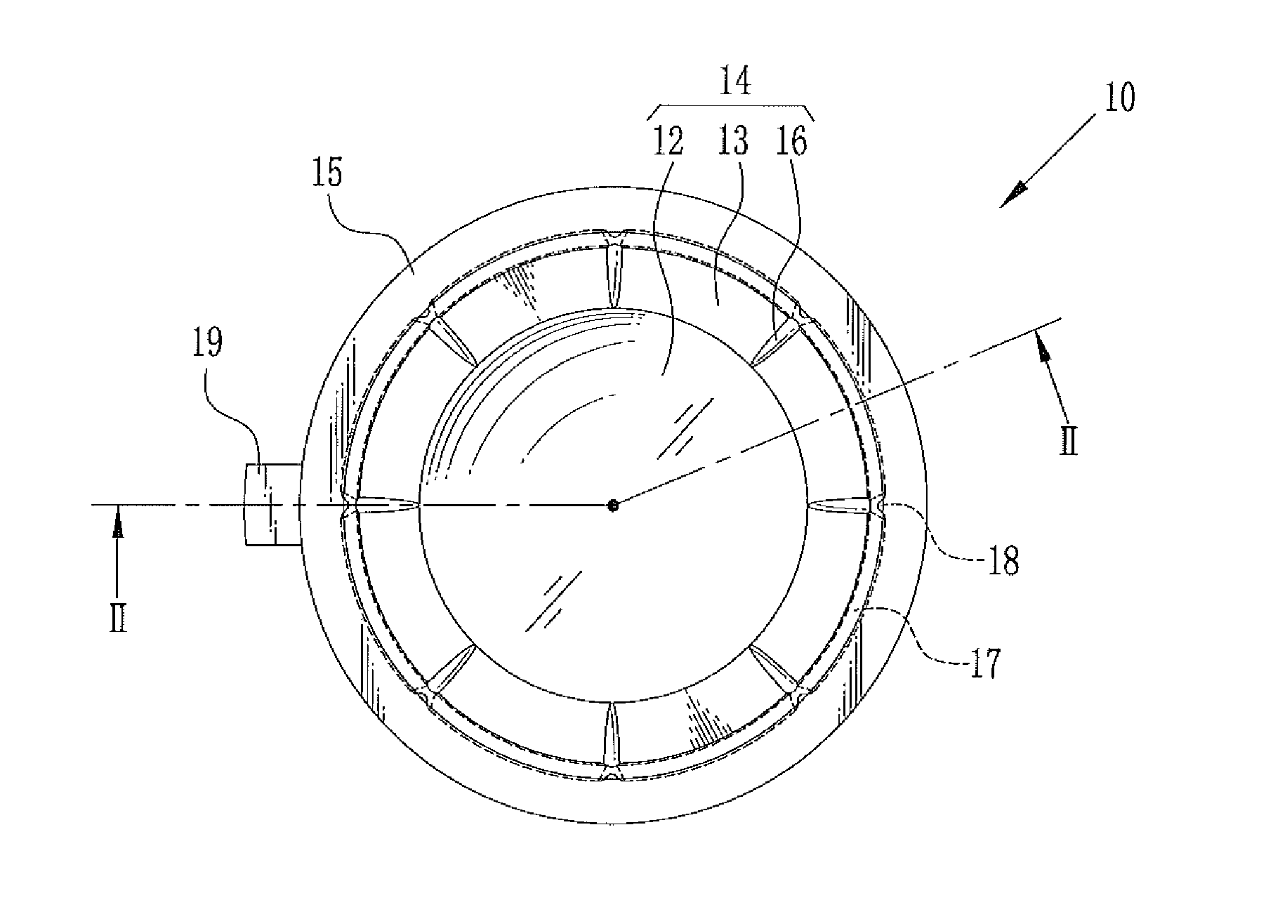
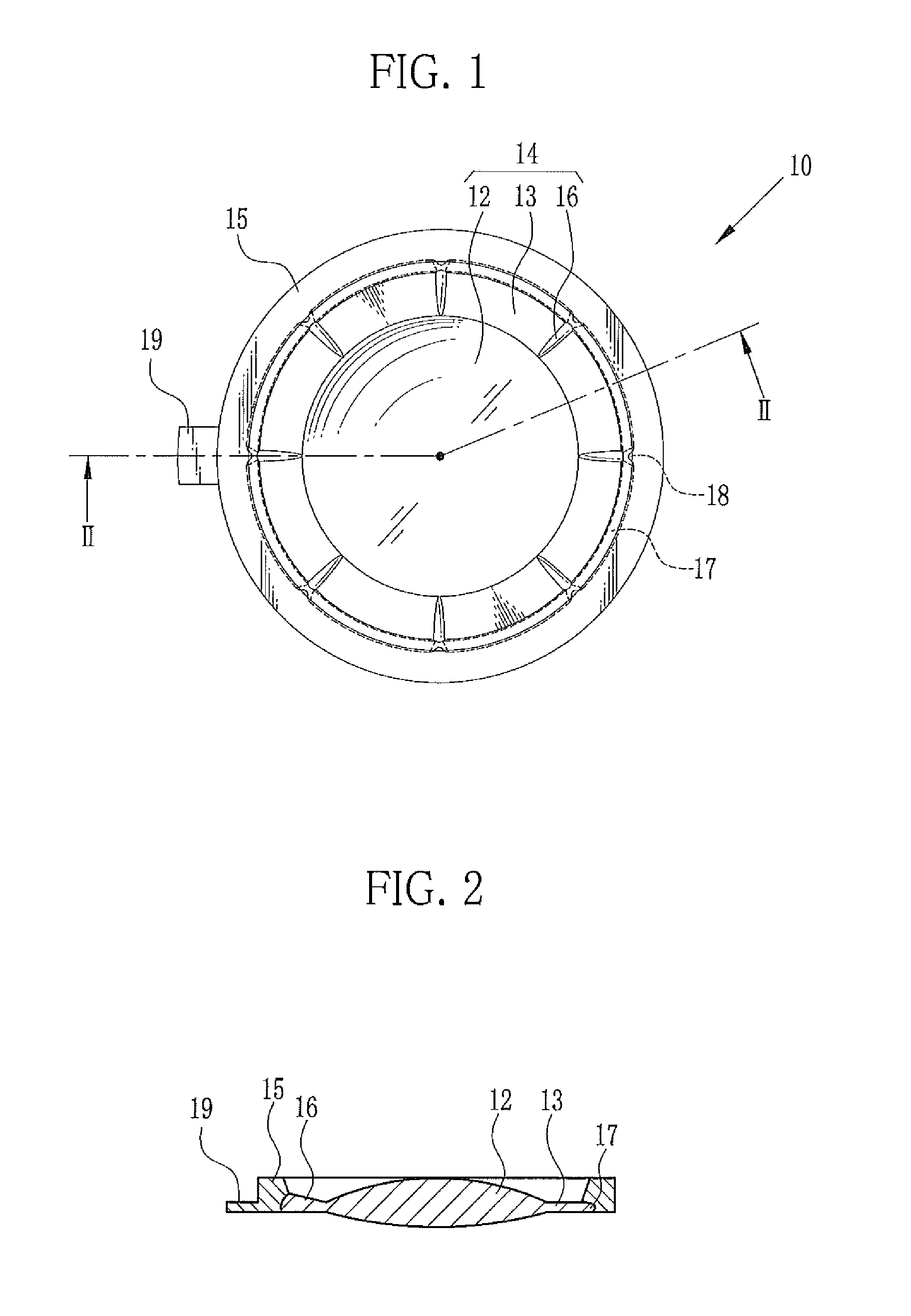
[0035]In FIGS. 1 and 2, a composite molded lens 10 comprises a lens body 14 and a lens frame (frame) 15. The lens body 14 is made by press-forming or press-molding a transparent preform. The lens frame 15 is made by injection molding. The lens body 14 has a lens portion 12 and a flange portion 13 surrounding the lens portion 12. The lens frame 15 is made from resin such as PMMA or PC through injection molding. The lens frame 15 is tightly joined to an outer peripheral portion of the flange portion 13. Note that opaque resin is commonly used for the lens frame 15. A gate portion 19 is formed due to the injection molding. The gate portion 19 is removed later as necessary.
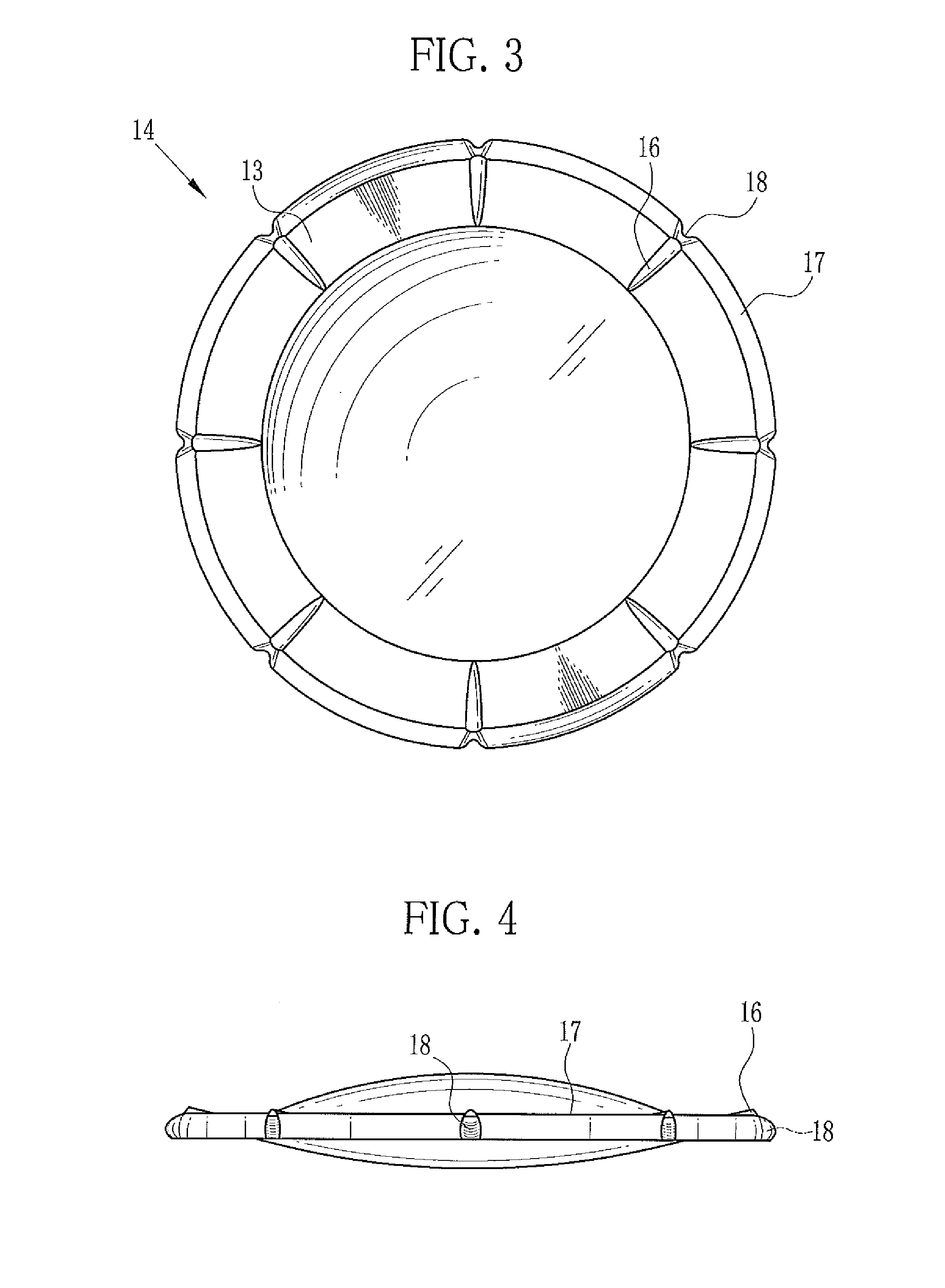
[0036]In FIGS. 3 and 4, there are eight projections 16 extending radially at 45° intervals on one surface of the flange portion 13 of the lens body 14. A planar shape of the projection 16 has a flat semi-ellipsoidal shape. A cross-section of the projection 16 has an upper convex segmental shape or a semi-ellipsoidal s...
second embodiment
[0043]In a second embodiment shown in FIGS. 8 to 12, the projections are formed on each surface of the flange portion. The positions of the projections on the top surface correspond to or coincide with those of the projections on the bottom surface. Note that the same reference numbers are used for the same parts as in the first embodiment. In FIGS. 8 and 9, a mold 30 is composed of a first mold 31 and a second mold 34. A gate opening 39 is formed in the second mold 34. The first mold 31 is the same as the first mold 21 of the first embodiment except that the lower edge of the first mold 31 is cut away by the thickness of the gate opening 39. The first mold 31 is formed with the transfer surface 22, the flange forming surface 23, the frame forming cavity 25, and the eight depressed portions 26. As shown in FIG. 9, the shape of the second mold 34 is the same as that of the first mold 21 of the first embodiment. The second mold 34 is formed with the transfer surface 27, a flange formi...
third embodiment
[0046]In a third embodiment shown in FIGS. 13 and 14, the projections 16 on the top surface of a flange portion 53 of a lens body 51 are shifted by ½ pitch (rotated by 22.5°) from the projections 46 on the bottom surface thereof. Thereby recesses 58a and 58b are formed alternately on the outer peripheral end face of an outer peripheral portion 57 of the flange portion 53. The recesses 58a and 58b are staggered from each other in an up-and-down direction. The recesses 58a and 58b make the free curved shape of the outer peripheral end face complex. As a result, the bonding force of the lens frame to the lens body 51 is further strengthened. Note that only the lens body 51 is depicted in FIGS. 13 and 14 because the lens frame is apparent from FIGS. 1 and 2.
PUM
| Property | Measurement | Unit |
|---|---|---|
| Depth | aaaaa | aaaaa |
| Height | aaaaa | aaaaa |
Abstract
Description
Claims
Application Information
 - R&D
- Intellectual Property
- Life Sciences
- Materials
- Tech Scout
- Unparalleled Data Quality
- Higher Quality Content
- 60% Fewer Hallucinations
Browse by: Latest US Patents, China's latest patents, Technical Efficacy Thesaurus, Application Domain, Technology Topic, Popular Technical Reports.
© 2025 PatSnap. All rights reserved.Legal|Privacy policy|Modern Slavery Act Transparency Statement|Sitemap|About US| Contact US: help@patsnap.com