Manufacturing apparatus and method of manufacturing a metal-composite patch part

a manufacturing apparatus and metal-composite technology, applied in the field of manufacturing apparatus and metal-composite patch parts, can solve the problems of limited application of ultra-high-strength steel sheets alone to secure performance, difficulty in bonding with metal, and high price, so as to improve mechanical interlocking effect, increase surface area, and increase the effect of adherence with composi

Pending Publication Date: 2022-06-09
HYUNDAI MOTOR CO LTD +1
View PDF5 Cites 0 Cited by
  • Summary
  • Abstract
  • Description
  • Claims
  • Application Information

AI Technical Summary

Benefits of technology

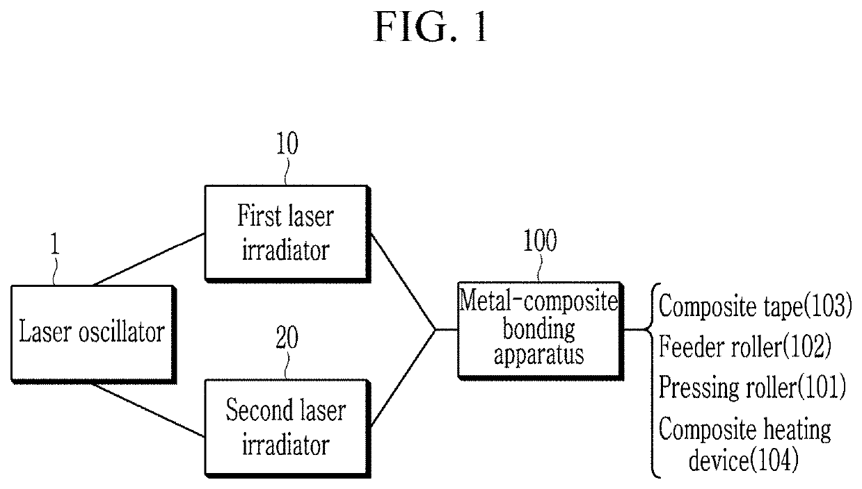
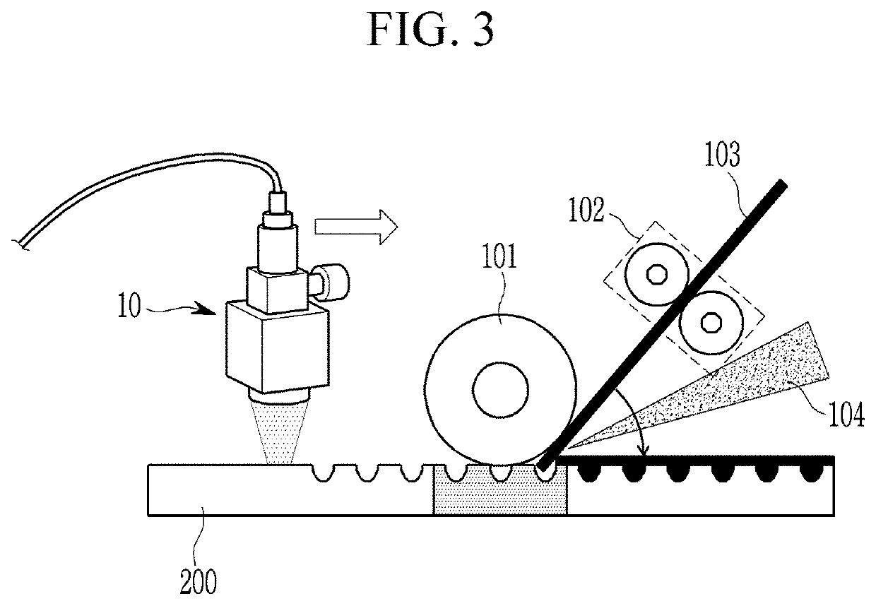
[0009]An embodiment of the present disclosure provides an apparatus capable of simultaneously heating a metal and a composite for bonding of the metal and the composite. Embodiments of the present disclosure also provide a manufacturing apparatus and a method of manufactur

Problems solved by technology

However, there is a limit to the application of the ultra-high-strength steel sheet alone to secure performance.
However, in the case of the composite, though the weight is light, the price is high, and there is a problem in which the bonding with the metal is difficult.
Thus, the productivity is very low.
However, the following problems exist in applying the AFP equipment to the metal composite.
Simultaneous heating is not possible due to the difference in

Method used


Image

  • Manufacturing apparatus and method of manufacturing a metal-composite patch part
  • Manufacturing apparatus and method of manufacturing a metal-composite patch part
  • Manufacturing apparatus and method of manufacturing a metal-composite patch part

Examples


embodiment 1

[0094]In the case of embodiment 1, the composite tape 103 including 50% by weight of the CFRP on the 980 MPa metal 200 plate applied to the surface of the metal 200 plate by 1 layer. The bending strength did not increase in this case and the bending energy increased by about 22% compared to the 980 MPa metal 200 plate without the composite tape 103.

[0095]In the case of embodiment 2, two layers of the composite tape 103 are applied to the surface of the metal 200 plate. In this case, the bending strength and the energy are slightly increased to 1745 N and 10.4 J, respectively, compared to embodiment 1, in which the composite tape 103 is coated with one layer. However, the lower bending strength showed a decrease compared to the plate material of the 1470 MPa metal without the applied composite tape 103.

embodiment 3

[0096]In the case of embodiment 3, the composite tape 103 was applied in three layers to the metal 200 plate surface. In this case, the bending strength was 2020 N, which exceeded the bending strength value of the 1470 MPa plate without the composite tape 103 applied. Also, the bending energy was 12.1 J, which was about 46% higher than that of the 980 MPa metal 200 plate without the composite tape 103 and was about 53% higher compared to the 1470 MPa metal 200 plate without the composite tape 103. Therefore, it may be seen that the 1470 MPa steel plate may be replaced when three layers of the composite tape 103 are applied using the 980 MPa metal plate.

[0097]FIGS. 13A-13D are views showing examples of vehicle parts applied with manufacturing method according to an embodiment of the present disclosure.

[0098]Referring to FIGS. 13A-13D, the vehicle parts to which the manufacturing apparatus and manufacturing method for the metal-composite patch part according to the present disclosure ...


PUM

PropertyMeasurementUnit
Percent by massaaaaaaaaaa
Poweraaaaaaaaaa

Abstract

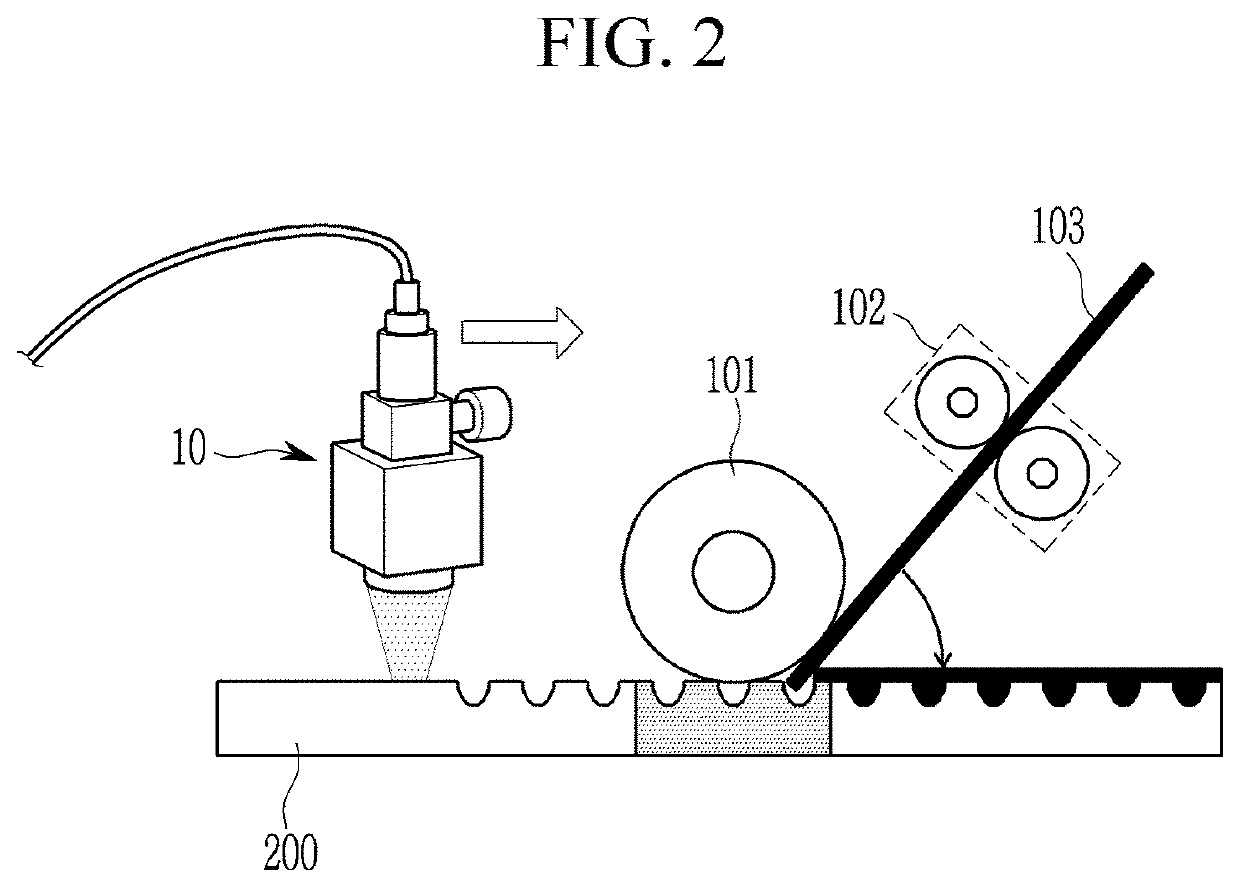
A manufacturing apparatus of a metal-composite patch part and a manufacturing method thereof include: a laser oscillator oscillating a laser; a first laser irradiator used to perform pattern processing on one surface of a metal with a laser by receiving the laser from the laser oscillator; and a metal-composite bonding apparatus for bonding a composite tape to the one surface of the pattern-processed metal. The apparatus includes a feeder roller supplying a composite tape to the one surface of the pattern processed metal and a pressing roller pressing the composite tape to the one surface of the metal. The bonding performance between the metal and the composite and productivity may be improved because the number of the processes related to the metal-composite patch part manufacturing process may be significantly reduced.

Description

CROSS-REFERENCE TO RELATED APPLICATION[0001]This application claims priority to and the benefit of Korean Patent Application No. 10-2020-0169604 filed in the Korean Intellectual Property Office on Dec. 7, 2020, the entire contents of which are incorporated herein by reference.BACKGROUND(a) Field of the Disclosure[0002]The present disclosure relates to a manufacturing apparatus and a method for manufacturing a metal-composite patch part. More particularly, the present disclosure relates to a manufacturing apparatus and a method of manufacturing a metal-composite patch part capable of increasing productivity by applying automated fiber placement (AFP) equipment, which is a composite part manufacturing technology.(b) Description of the Related Art[0003]To enhance fuel efficiency of internal combustion engine vehicles and improve a range of electric and hydrogen vehicles, vehicle body weight reduction continues to be an issue in the vehicle industry. In order to reduce the weight of the...

Claims


Application Information

Patent Timeline
IPC IPC(8): B23K26/08B23K26/362B23K26/352B23K26/0622
CPCB23K26/0853B23K26/362B23K2103/18B23K26/0622B23K26/355B29C66/742B29C66/4722B29C65/44B29C66/1122B29C65/1416B29C65/1409B29C65/1432B29C66/0246B29C66/30322B29C66/7392B29C66/7212B29C66/72141B29C66/8362B29C65/72B29C66/0242B29C65/1458B29K2307/04B29C70/386B23K26/352B29C66/0224B29C70/388B29C70/40B29C65/02B29C66/721B29C66/8322B29K2105/12B29K2105/0872
Inventor JEONG, JUNYEONGJUNG, YOUN IL
Owner HYUNDAI MOTOR CO LTD
Why Eureka
Try Eureka