
Time synchronization between nodes of a switched interconnect fabric

Inactive Publication Date: 2014-11-27
III HLDG 2
View PDF4 Cites 17 Cited by
  • Summary
  • Abstract
  • Description
  • Claims
  • Application Information

AI Technical Summary

Benefits of technology

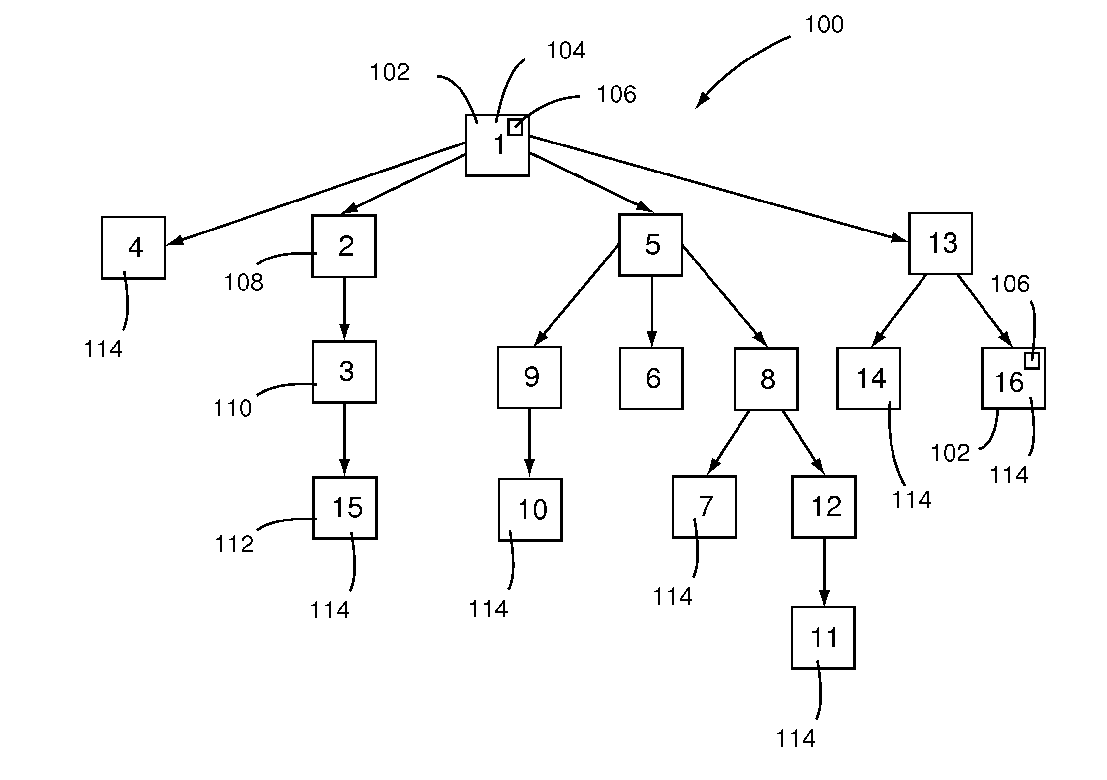
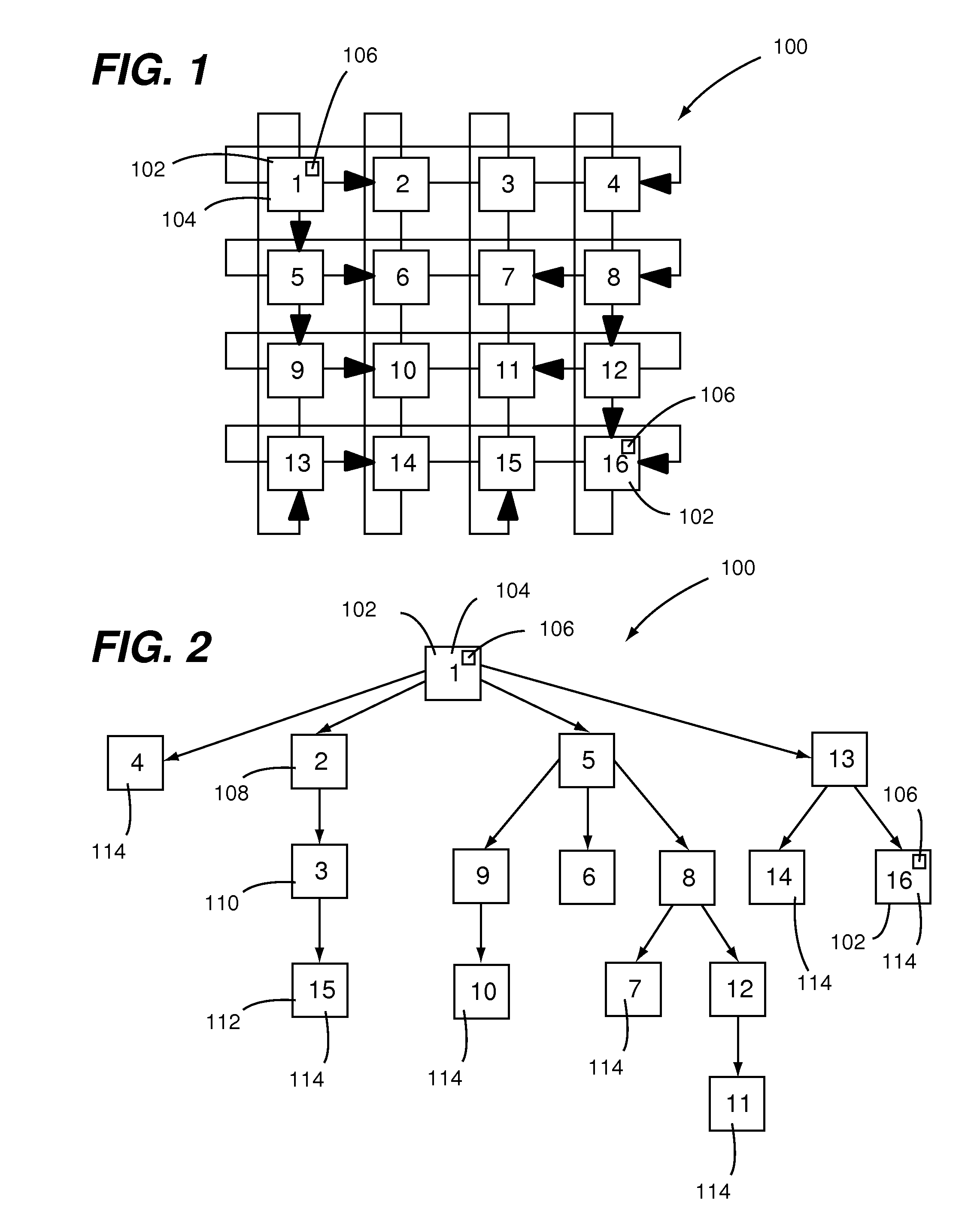
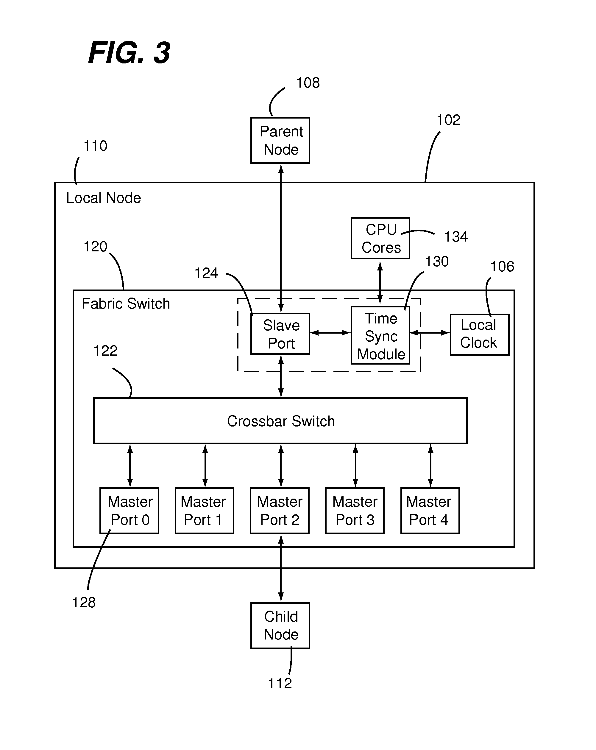
The present invention provides a way to synchronize the clocks of nodes in a fabric, which results in a common chronological timeline and reduces system noise and latencies. The synchronization is achieved using a distributed service running on all nodes across the fabric, with each node having its own local clock. The time synchronization service is a hardware-implemented service, which allows for faster convergence of nodes in the fabric. The data processing node comprises a local clock and a time synchronization module that collects parent-centric time synchronization information and uses it to implement time-based functionality in accordance with the fabric time.

Problems solved by technology

Accordingly, accuracy of time synchronization affects overall system noise and application level latencies.
For example, it is difficult to accurately debug performance problems in a cluster of nodes if time is not accurately synchronized across the nodes (e.g., servers, which can be in the form of a SOC).
However, when time synchronization is provided as a software-implemented service within the nodes, time synchronization accuracy is adversely impacted due to limitations arising from processing information within the software.
Furthermore, in a time synchronization implementation such as that in accordance with IEEE 1588, there are several factors that can contribute to significant computational error and this error can also accumulate over time thereby resulting in loss of accuracy.
In addition, the variable latency involved in reading timestamps from software has a significant adverse effect on the accuracy of time synchronization.
However, atomic clocks are relatively expensive and, thus, it can be impractical to have one atomic clock per node.
Instead, it is common to use one atomic clock per rack of nodes (e.g., servers), which can be counter-productive as this leads to lost time synchronization accuracy.

Method used


Image

  • Time synchronization between nodes of a switched interconnect fabric
  • Time synchronization between nodes of a switched interconnect fabric
  • Time synchronization between nodes of a switched interconnect fabric

Examples


Embodiment Construction

[0023]Embodiments of the present invention are directed to implementation of a time synchronization (sync) protocol entirely or predominately in hardware (HW) of each one of a plurality of data processing nodes in a network. Server on a chip (SoC) nodes that are interconnected within a fabric via a respective fabric switch are examples of a data processing node in the context of the present invention. However, the present invention is not unnecessarily limited to any particular type, configuration, or application of data processing node.

[0024]Advantageously, with a HW implementation of time synchronization, a relatively high rate of time sync packet exchanges can be maintained between data processing nodes. This enables an entire cluster of processing nodes to converge to a common time much faster than in a purely software (SW) implementation of time synchronization. Furthermore, a HW implementation of time synchronization provides a mechanism for synchronizing a local clock of each...


PUM


Abstract

A data processing node includes a local clock, a slave port and a time synchronization module. The slave port enables the data processing node to be connected through a node interconnect structure to a parent node that is operating in a time synchronized manner with a fabric time of the node interconnect structure. The time synchronization module is coupled to the local clock and the slave port. The time synchronization module is configured for collecting parent-centric time synchronization information and for using a local time provided by the local clock and the parent-centric time synchronization information for allowing one or more time-based functionality of the data processing node to be implemented in accordance with the fabric time.

Description

BACKGROUND[0001]1. Field of the Invention[0002]Embodiments of the present invention relate to a switched interconnect fabric and nodes thereof. More specifically, embodiments of the present invention relate to implementation of time synchronization between nodes of a switched interconnect fabric such as a cluster of fabric-attached Server on a Chip (SoC) nodes.[0003]2. Description of Related Art[0004]It is well known that time synchronization between a cluster of interconnected nodes (i.e., a distributed system) is important to the effectiveness and accuracy of operation of such nodes. For example, accuracy of time synchronization between nodes (i.e., clocks thereof) affects synchronization of OS schedulers across the fabric. Accordingly, accuracy of time synchronization affects overall system noise and application level latencies.[0005]Several aspects of distributed systems or clusters can be affected by time synchronization. Event tracing, debugging, synchronization between thread...

Claims


Application Information

Patent Timeline
IPC IPC(8): H04J3/06
CPCH04J3/0697H04J3/0667
Inventor CHANDRA, PRASHANT R.VOLPE, THOMAS A.DAVIS, MARK BRADLEY
Owner III HLDG 2
Learn More