Unlock instant, AI-driven research and patent intelligence for your innovation.

High Energy Cathode for a Battery

a high-energy cathode and battery technology, applied in the field of battery technology, can solve the problems of limiting the widespread use and realization of the performance potential of metal fluoride materials, poor rate performance, and low rate, and achieves low voltage drop, low rate, and high discharge rate

Active Publication Date: 2014-11-27
WILDCAT DISCOVERY TECH
View PDF3 Cites 6 Cited by
  • Summary
  • Abstract
  • Description
  • Claims
  • Application Information

AI Technical Summary

Benefits of technology

The patent text describes a method for making an electrode for an electrochemical cell by coating an active electrode material with a conductive coating. The coating is made from an organic coating compound that has a conjugated core. The coated electrode material is then combined with a binder material and a conductive additive to form an electrode-forming mixture. The mixture is heated to form the electrode. The invention also involves a method of making a composition for use in forming a cathode for a battery by milling a metal fluoride material with a metal complex and annealing the mixture. The resulting composition has reversible capacity and includes particles with a particle size and a coating on the particle that includes the metal oxide. The invention also describes an electrochemical cell containing coated cathode materials and methods of using the same. The technical effects of the invention include improving the performance of electrochemical cells and providing stable and reversible capacity.

Problems solved by technology

However, a number of technical challenges currently limit their widespread use and realization of their performance potential.
One challenge for certain metal fluoride materials is comparatively poor rate performance.
Unfortunately, one of the drawbacks to wide bandgap materials is the intrinsically low electronic conductivity that results from the wide bandgap.
Such low discharge rates limit the widespread use of metal fluoride active materials.
Another challenge for certain metal fluoride active materials is a significant hysteresis observed between the charge and discharge voltages during cycling.
Since the electrochemical potential for many of the metal fluorides is on the order of 3.0V, this hysteresis of about 1.0V to about 1.5V limits the overall energy efficiency to approximately 50%.
Limited cycle life is another challenge for certain metal fluoride active materials.
Although rechargeability has been demonstrated for many metal fluoride active materials, their cycle life is typically limited to tens of cycles and is also subject to rapid capacity fade.
Two mechanisms are currently believed to limit the cycle life for the metal fluoride active materials: agglomeration of metallic nanoparticles and mechanical stress due to volume expansion.
The larger agglomerated particles in turn create islands that are electrically disconnected from one another, thus reducing the capacity and ability to cycle the metal fluoride active materials.
The second limitation to extended cycle life is the mechanical stress imparted to the binder materials by the metal fluoride particles as a result of the volume expansion that occurs during the conversion reaction.
Over time, the binder is pulverized, compromising the integrity of the cathode.

Method used


Image

  • High Energy Cathode for a Battery
  • High Energy Cathode for a Battery
  • High Energy Cathode for a Battery

Examples


example 1

Fabrication of Matrix and / or Coated Electrodes for Rechargeable Cells

[0092]Materials and Synthetic Methods.

[0093]All reactions were prepared in a high purity argon filled glove box (M-Braun, O2 and humidity contents <0.1 ppm). Unless otherwise specified, materials were obtained from commercial sources (e.g., Sigma-Aldrich, Advanced Research Chemicals Inc., Alfa Aesar, Strem) without further purification.

[0094]Preparation of CuF2 / Matrix.

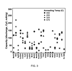
[0095]Milling vessels were loaded with CuF2 at from about 85 wt % to about 95 wt % and reactant (metal oxide or metal oxide precursor) at from about 5 wt % to about 15 wt %, and the vessels were sealed. The mixture was milled. After milling, samples were annealed at from about 200 degrees C. to about 575 degrees C. for 1 to 12 hours under flowing N2. Specific matrix reactants were processed as described below.

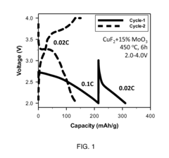
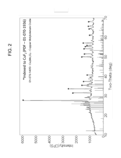
[0096]Preparation of CuF2 / CusMo2O9.

[0097]Milling vessels were loaded with CuF2 (85 wt %) and MoO3 (15 wt %), sealed, and then milled. After mill...

example 2

Electrochemical Characterization of Electrochemical Cells Containing Rechargeable Electrodes

[0104]All batteries were assembled in a high purity argon filled glove box (M-Braun, O2 and humidity contents <0.1 ppm), unless otherwise specified. Cells were made using lithium as an anode, Celgard 2400 separator, and 90 μL of 1M LiPF6 in 1:2 EC:EMC electrolyte. Electrodes and cells were electrochemically characterized at 30 degrees C. with a constant current C / 50 charge and discharge rate for the first 2 cycles and C / 5 charge and discharge rate for the following cycles between 4.0 V and 2.0 V. A 3 hour constant voltage step was used at the end of each charge. In some instances, cathodes were lithiated pressing lithium foil to the electrode in the presence of electrolyte (1M LiPF6 in 1:2 EC:EMC) for about 15 minutes. The electrode was then rinsed with EMC and built into cells as described above, except graphite was used as the anode rather than lithium.

example 3

Fabrication of Conductively Coated Metal Fluoride Electrodes

[0105]Materials and Synthetic Methods.

[0106]All reactions were prepared in a high purity argon filled glove box (M-Braun, O2 and humidity contents <0.1 ppm). Unless otherwise specified, materials were obtained from commercial sources (Sigma-Aldrich, Advanced Research Chemicals Inc, Alfa Aesar, Strem, etc) without further purification.

[0107]Preparation of Conductively Coated CuF2 / NiO.

[0108]Milling vessels were loaded with CuF2, NiO, and conductive coating precursor at the desired ratios, sealed, and then milled for about 20 hours. The milling vessels were opened under argon gas and the conductive coating precursor materials were added. The milling vessels were sealed and milled at low energy. After milling, the powder samples were annealed (for example, at 325 degrees C. for 6 hours).

[0109]Electrode Formulation.

[0110]In some embodiments, cathodes were prepared using a formulation composition of 80:15:5 (active material:binde...


PUM

PropertyMeasurementUnit
grain sizeaaaaaaaaaa
energy densitiesaaaaaaaaaa

Abstract

An electrode for an electrochemical cell including a metal fluoride containing active electrode material and an intrinsically conductive coating wherein the coating is applied to the active electrode material by heating the mixture for a time and at a temperature that limits degradation of the cathode active material. The active material can be a hybrid material formed from the reaction of a metal fluoride and a metal complex.

Description

CROSS-REFERENCE TO RELATED APPLICATIONS[0001]This application is a continuation-in-part of copending International Application No. PCT / US2014 / 028271, having an international filing date of Mar. 14, 2014 entitled “Cathode for a Battery,” which in turn claims priority to copending U.S. application Ser. No. 13 / 831,924 filed Mar. 15, 2013 entitled “Cathode for a Battery,” which is a continuation-in-part of co-pending U.S. application Ser. No. 13 / 612,800 filed Sep. 12, 2012 entitled “Cathode for a Battery,” which in turn claims priority to and the benefit of U.S. Provisional Application No. 61 / 533,911 filed Sep. 13, 2011 entitled “Cathode for Metal-Fluoride Battery” and U.S. Provisional Application No. 61 / 621,205 filed Apr. 6, 2012 entitled “Cathode for a Battery.”[0002]This application is a continuation-in-part of International Application No. PCT / US2014 / 028506, having an international filing date of Mar. 14, 2014 entitled “High Energy Materials For A Battery And Methods For Making And ...

Claims


Application Information

Patent Timeline
Patent Type & Authority Applications(United States)
IPC IPC(8): H01M4/36H01M4/62H01M4/04H01M4/58H01M4/525
CPCH01M4/366H01M4/582H01M4/0402H01M4/0471H01M4/624H01M4/525H01B1/122H01M4/08H01M4/382H01M4/505H01M4/5835H01M4/5825H01M4/583H01M4/625Y02E60/10Y02P70/50
Inventor O'NEILL, CORYKAYE, STEVENCALDWELL, MARISSAKEOGH, DAVID
Owner WILDCAT DISCOVERY TECH