Exhaust gas heat recovery device

a heat recovery device and exhaust gas technology, applied in indirect heat exchangers, machines/engines, lighting and heating apparatus, etc., can solve the problems of heat loss recovery, inadequate heat exchange, etc., and achieve the effect of inhibiting exhaust gas heat, short time, and improving efficiency in recovering exhaust gas hea

Active Publication Date: 2014-12-04
FUTABA IND CO LTD
View PDF10 Cites 9 Cited by
  • Summary
  • Abstract
  • Description
  • Claims
  • Application Information

AI Technical Summary

Benefits of technology

[0013]In the exhaust gas heat recovery device of the present invention, the respective heat exchange medium conduits in the plurality of the jacket parts are serially connected to each other, whereby the heat exchange medium flows through one long heat exchange medium conduit as a whole flow path. Therefore, heat exchange is performed between the heat exchange medium and the exhaust gas each time the heat exchange medium flows through the heat exchange medium conduit in each of the jacket parts. Thus, exhaust gas heat is adequately recovered and a temperature of the heat exchange medium increases in a short time, whereby improving efficiency in recovering the exhaust gas heat.
[0014]Further, the exhaust gas having a high temperature from the exhaust pipe flows into the clearance (the first clearance) between the outer circumference of the exhaust pipe and the stacked body. Therefore, it is possible to inhibit the exhaust gas heat from being released to the atmosphere, whereby a recovery loss of an exhaust gas heat amount to be recovered can be decreased. In regard to the above, an effect of improving the efficiency in recovering the exhaust gas heat can be achieved.
[0015]The stacked body is composed by stacking the plurality of jacket parts each having a flattened-shape, whereby the device can be downsized despite that the long heat exchange medium conduit is provided. Further, the two jacket part assemblies are stacked on the end part having the heat exchange medium conduit provided thereinside, whereby the device can be downsized despite that the long heat exchange medium conduit is provided.

Problems solved by technology

For example, in a case that much of the heat exchange medium flows through some of the short flow paths provided in parallel, the heat exchange is not adequately performed.
Therefore, a recovery loss of a heat amount occurs.

Method used


Image

  • Exhaust gas heat recovery device
  • Exhaust gas heat recovery device
  • Exhaust gas heat recovery device

Examples


Embodiment Construction

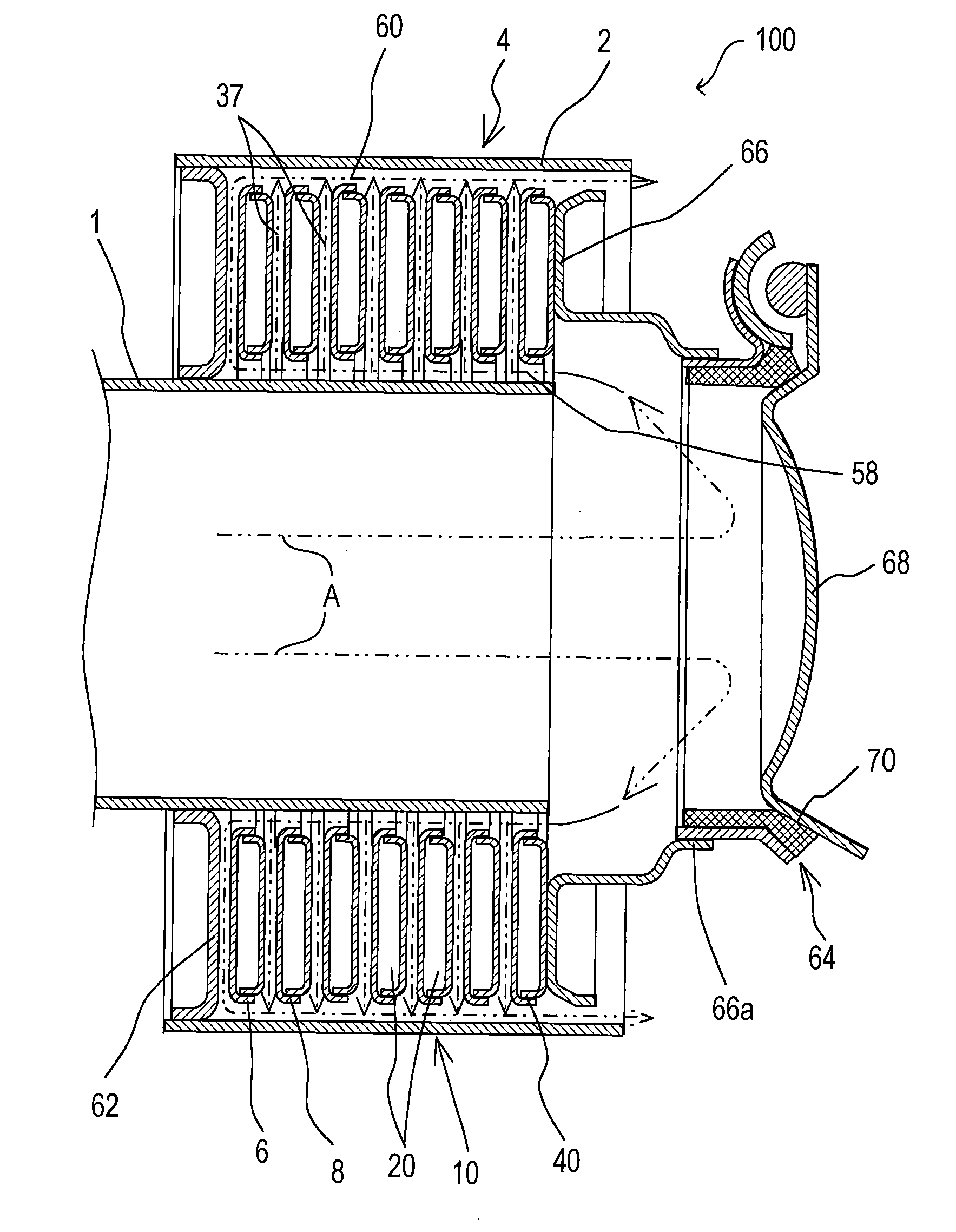
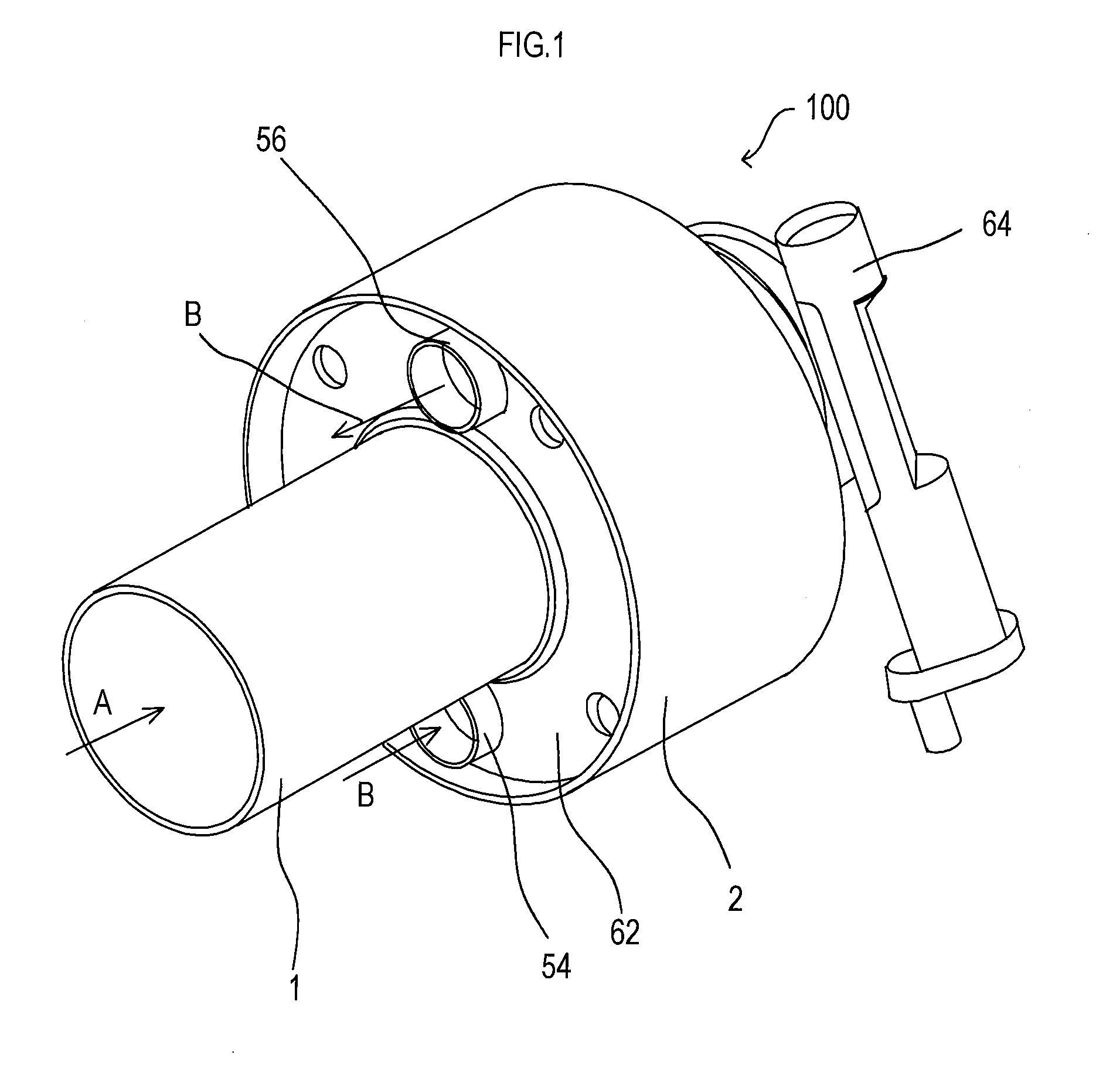
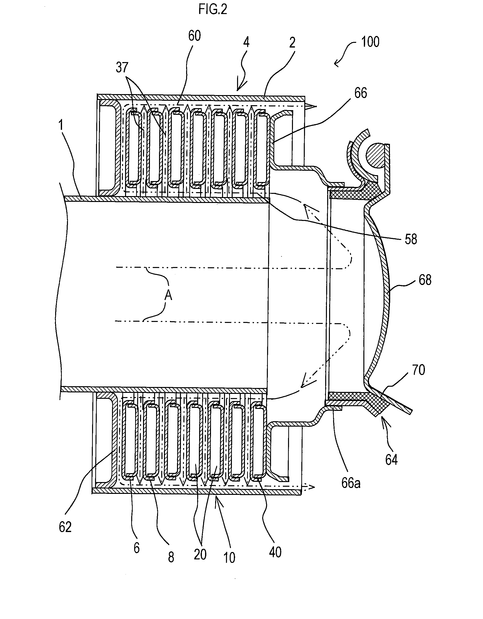
[0023]Hereinafter, a mode for carrying out the present invention will be described in detail with reference to the drawings.

[0024]As shown in FIGS. 1 and 2, an exhaust gas heat recovery device 100 includes an exhaust pipe 1, a cylindrical shell 2, and an exhaust gas heat recovery section 4, as main components. An upstream side of the exhaust pipe 1 is connected to an exhaust-gas flow path from an internal combustion engine, and the exhaust pipe 1 is configured such that an exhaust gas A from the internal combustion engine is led from an upstream side to a downstream side. Outside of the exhaust pipe 1, there is provided the cylindrical shell 2 that surrounds the exhaust pipe 1. The exhaust pipe 1 is disposed inside of the cylindrical shell 2, which is provided so as to be spaced from the exhaust pipe 1, whereby a space is provided between an outer circumference of the exhaust pipe 1 and an inner circumference of the cylindrical shell 2. In the present embodiment, the exhaust pipe 1 ...


PUM


Abstract

An exhaust gas heat recovery device of the present invention recovers heat of an exhaust gas from an internal combustion engine. The exhaust gas heat recovery device includes an exhaust pipe that leads the exhaust gas from an upstream side to a downstream side, a cylindrical shell that covers an outside of the exhaust pipe, and an exhaust gas heat recovery section that is interposed between the exhaust pipe and the cylindrical shell and that performs heat exchange between the exhaust gas and a heat exchange medium. The exhaust gas heat recovery section includes a stacked body that is composed by stacking a plurality of jacket each having a heat exchange medium conduit provided thereinside. In the stacked body, the respective heat exchange medium conduits in the plurality of jacket parts are serially connected to each other.

Description

CROSS-REFERENCE TO RELATED APPLICATIONS[0001]This international application claims the benefit of Japanese Patent Application No. 2011-281468 filed Dec. 22, 2011 in the Japan Patent Office, and the entire disclosure of Japanese Patent Application No. 2011-281468 is incorporated herein by reference.TECHNICAL FIELD[0002]The present invention relates to an exhaust gas heat recovery device interposed in an exhaust-gas flow path from an internal combustion engine, which device recovers exhaust gas heat by performing heat exchange between exhaust gas and a heat exchange medium.BACKGROUND ART[0003]As described in Patent Document 1, there is a well-known device interposed in an exhaust-gas flow path, which device recovers exhaust gas heat by performing heat exchange between the exhaust gas from an internal combustion engine and a heat exchange medium, such as cooling water of the internal combustion engine and the like. In this device, a tube stacked body is composed by stacking a plurality...

Claims


Application Information

Patent Timeline
Patent Type & Authority Applications(United States)
IPC IPC(8): F01N5/02
CPCF01N5/02F01N2240/02F28D9/0012F28D9/0043F28D21/0003F28F27/00Y02T10/12
Inventor KATO, HISAYUKIOKAMI, HIROHISA
Owner FUTABA IND CO LTD
Why Eureka
Try Eureka