Eureka AIR delivers breakthrough ideas for toughest innovation challenges, trusted by R&D personnel around the world.

Te- polarization splitter based on photonic crystal waveguide

a polarization splitter and photonic crystal waveguide technology, applied in the field of micro optical polarization splitters, can solve the problems of large volume inability to use optical integrated circuits, and difficult integration of conventional polarization splitters into other photonic crystal devices, etc., to achieve convenient integration, small dimension, and high efficiency

Inactive Publication Date: 2014-12-04
SHENZHEN UNIV
View PDF6 Cites 6 Cited by
  • Summary
  • Abstract
  • Description
  • Claims
  • Application Information

AI Technical Summary

Benefits of technology

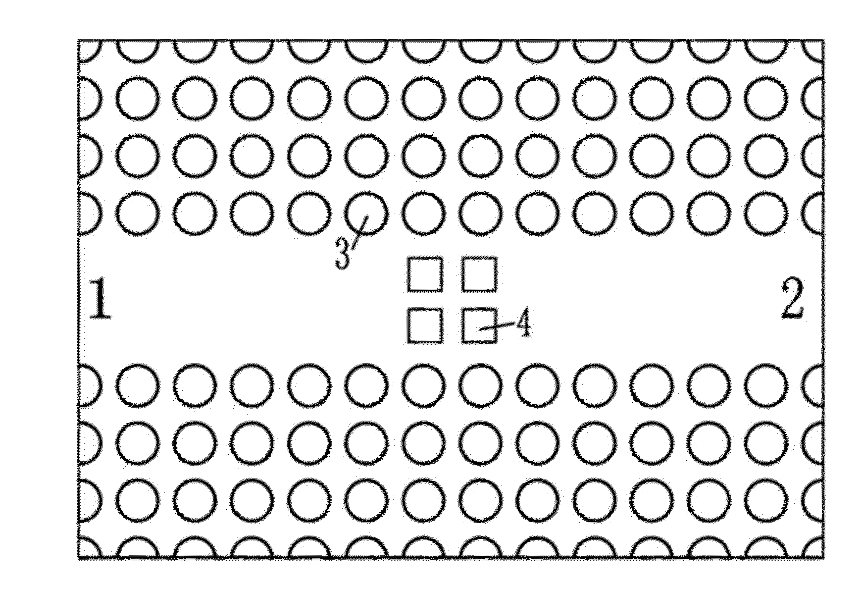
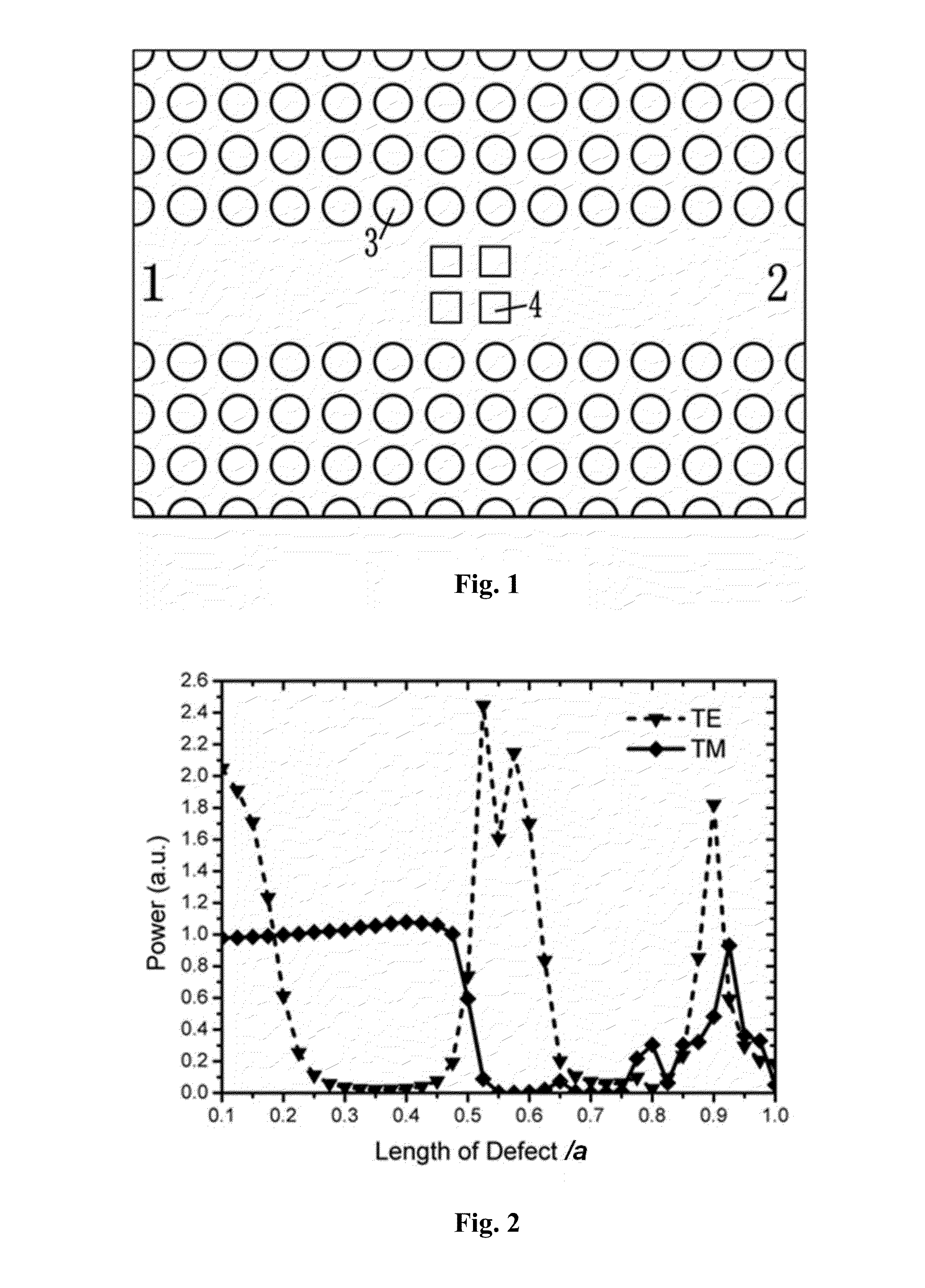
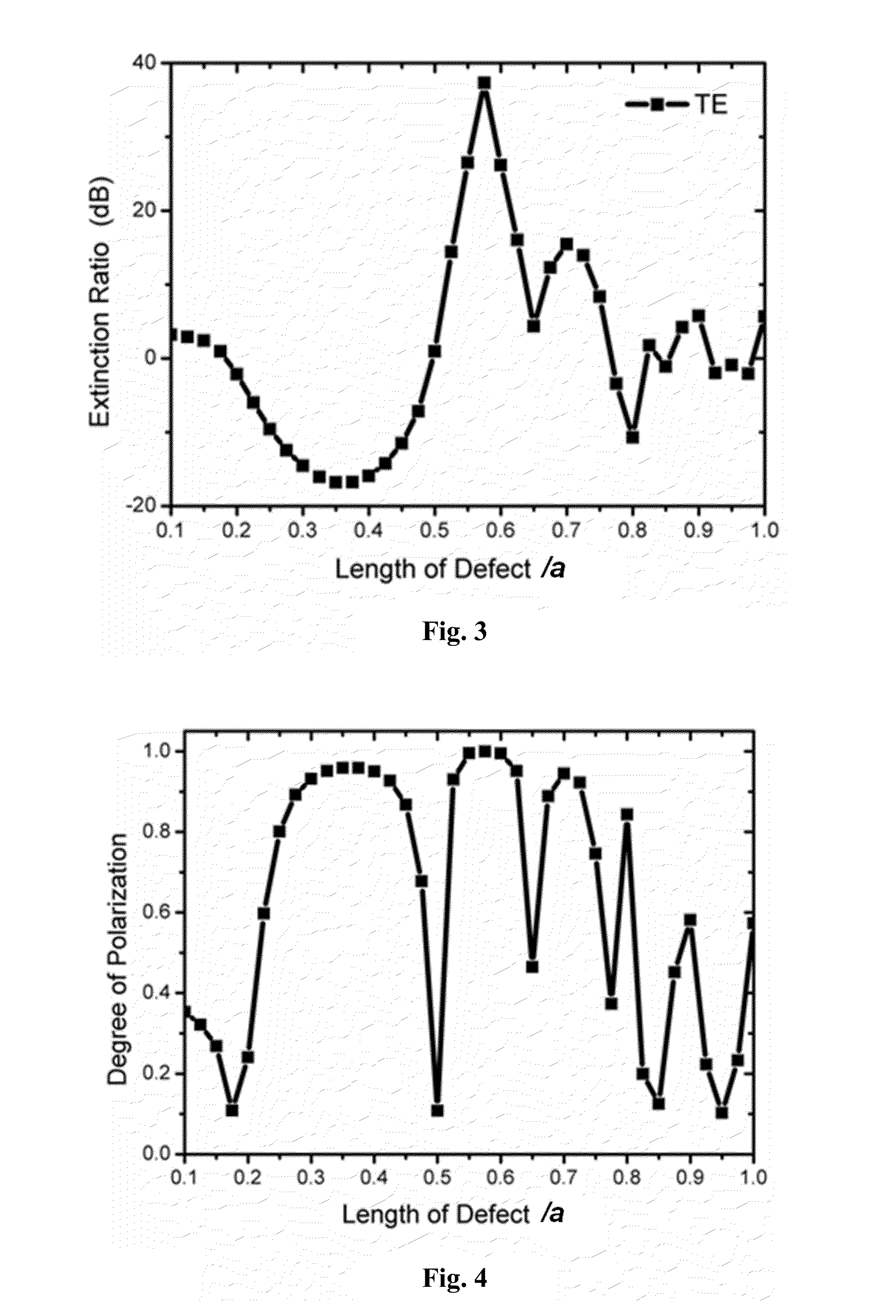
The present invention provides a TE-polarization splitter based on a photonic crystal waveguide that overcomes the shortcomings of prior art. It has the advantages of small size, high degree of polarization, high light transmission efficiency, and being suitable for large-scale optical integrated circuits. The invention can realize the polarization separation function through a kind of dielectric defect rods in a small volume, which is convenient for optical integration and high efficiency. Furthermore, the invention can realize the polarization beam splitting function for different wavelengths by scaling the lattice constant and other geometric parameters utilizing the scaling property of photonic crystals.

Problems solved by technology

Conventional polarization splitters are large in volume, and can not be used in the optical integrated circuits.
This kind of polarization splitters can only be used as separate photonic crystal devices, since the transmittance and degree of polarization are poor, and it is difficult to integrate them into other photonic crystal devices.

Method used


Image

  • Te- polarization splitter based on photonic crystal waveguide
  • Te- polarization splitter based on photonic crystal waveguide
  • Te- polarization splitter based on photonic crystal waveguide

Examples


Embodiment Construction

[0024]Below in connection with the accompanying drawings and specific embodiments, the present invention will be described in further detail.

[0025]The dielectric material in the principle introduction and the embodiments of the present invention is Te dielectric rod as an example. Tellurium is a uniaxial positive crystal, the refractive index for o-light thereof is no=4.8, and the refractive index for e-light is ne=6.2. For the e-axis and the dielectric rod axis in the same direction, the photonic bandgap can be obtained by the plane wave expansion. For the square-lattice photonic crystal with the lattice constant being a and the radius of the rods in photonic crystal being 0.3568a, the photonic bandgap is 3.928 to 4.550 (ωa / 2πc), and the light wave with any frequency therein will be confined in the waveguide.

[0026]In the present invention, square dielectric defect rods are introduced in the waveguide, such that the equivalent refractive indexes of the defect rods for the light wave...


PUM


Abstract

The present invention discloses a TE-polarization splitter based on a photonic crystal waveguide, comprising a waveguide formed in a photonic crystal with a complete photonic bandgap, wherein after the incident wave with any polarization direction is inputted into the polarization splitter via the input port of the photonic crystal waveguide. TE wave is outputted from the output port of the polarization splitter, while the TM wave is reflected from the input port of the polarization splitter. The structure of the present invention has a small volume, high degree of polarization, high light transmission efficiency, and it is suitable for large-scale optical integrated circuits and can realize the polarization beam splitting function for different wavelengths.

Description

FIELD OF THE INVENTION[0001]The invention relates to the field of micro optical polarization splitter, in particular, to a tiny optical polarization splitter based on photonic crystal technology.BACKGROUND OF THE INVENTION[0002]Conventional polarization splitters are large in volume, and can not be used in the optical integrated circuits. However, micro optical devices including polarization splitters can be manufactured based on photonic crystals. Up to now, there are two methods, one of which is that a photonic crystal with a TE photonic bandgap and a TM transmission band, or a TM photonic bandgap and a TE transmission band are used to achieve the polarization separation of waves. This kind of polarization splitters can only be used as separate photonic crystal devices, since the transmittance and degree of polarization are poor, and it is difficult to integrate them into other photonic crystal devices. The other is that different relative coupling lengths are designed in order to...

Claims


Application Information

Patent Timeline
IPC IPC(8): G02B6/126G02B6/122
CPCG02B6/1225G02B6/126G02B6/2773G02B2006/1215B82Y20/00G02B1/005G02B5/00G02B27/283
Inventor OUYANG, ZHENGBIAOJIN, XIN
Owner SHENZHEN UNIV
Why Eureka
Eureka Blog
Learn More