

Superconducting wire and superconducting coil
a superconducting wire and coil technology, applied in the direction of superconducting magnets/coils, cables, power cables, etc., can solve the problems of superconductor wire deterioration, mechanical characteristics, bending and twisting,
- Summary
- Abstract
- Description
- Claims
- Application Information
AI Technical Summary
Benefits of technology
Problems solved by technology
Method used
Image

Examples
first embodiment
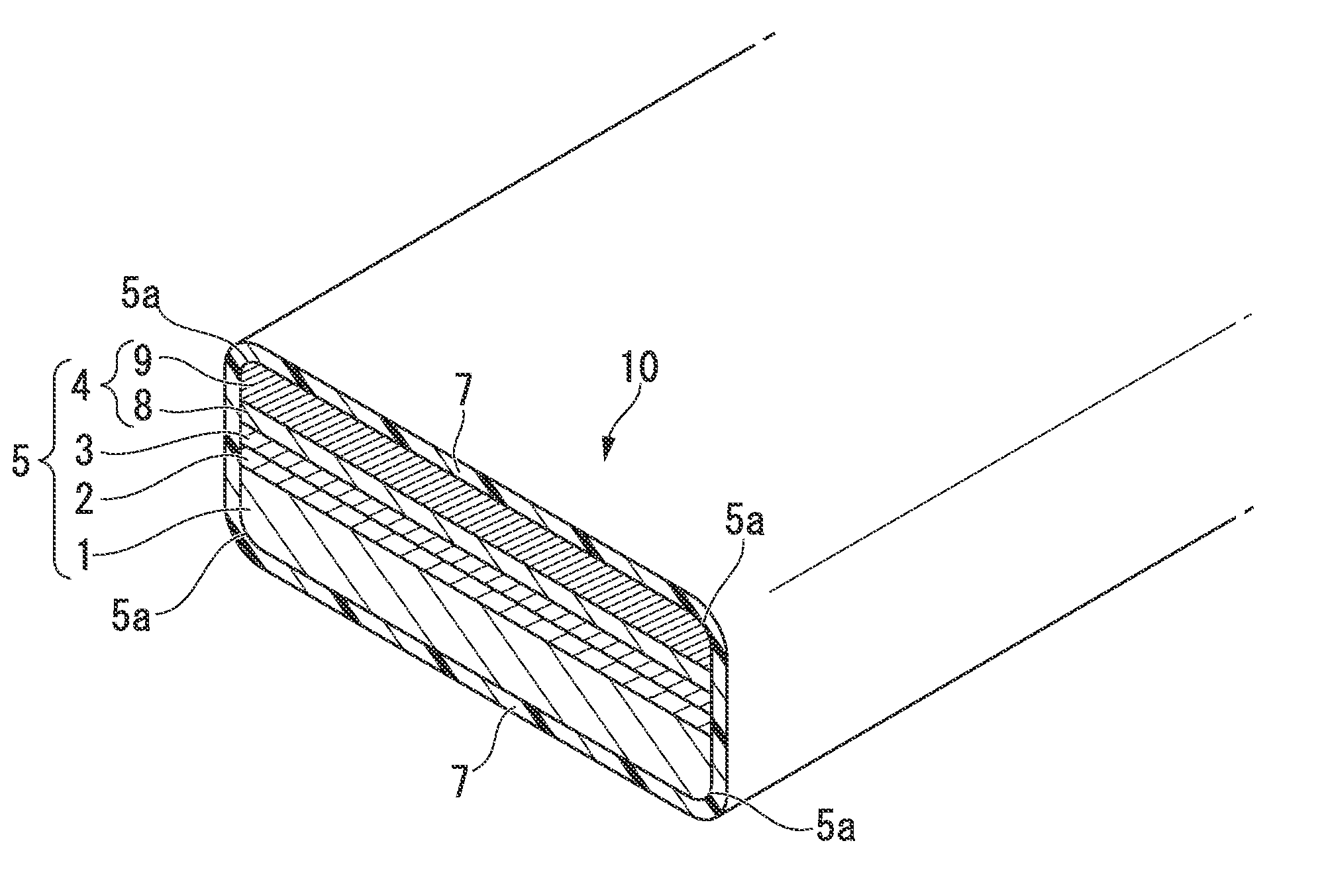
[0041]FIG. 1 is a perspective view of a partial cross section along the width direction of a superconductor wire according to a first embodiment of the present invention. In a superconductor wire 10 shown in FIG. 1, a superconducting laminate 5 is formed by laminating an intermediate layer 2, an oxide superconductor layer 3, and a metal stabilization layer 4 in this order on one surface of a substrate 1. That is, the intermediate layer 2 is formed on one surface of the substrate 1, the oxide superconductor layer 3 is formed on the outer side of the intermediate layer 2, and the metal stabilization layer 4 is formed on the outer side of the oxide superconductor layer 3. In addition, the superconductor wire 10 is formed by covering the entire outer surface of the superconducting laminate 5 with an insulation coating layer 7. In the present embodiment, the metal stabilization layer 4 is formed by a first stabilization layer 8 formed on the oxide superconductor layer 3 and a second stab...
second embodiment
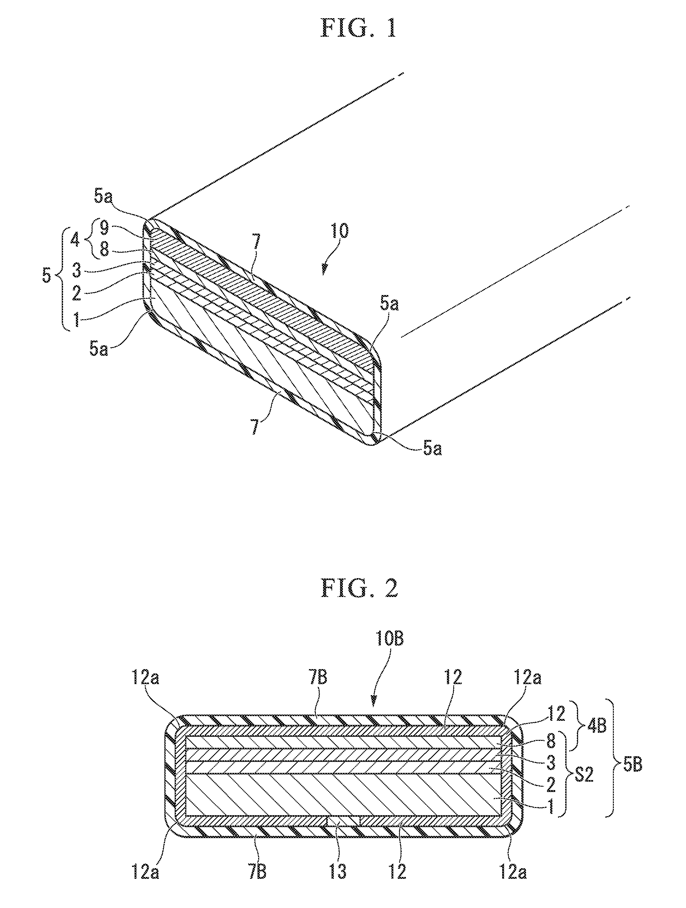
[0079]FIG. 2 is a schematic cross-sectional view along the width direction of a superconductor wire according to a second embodiment of the present invention.
[0080]In a superconductor wire 10B shown in FIG. 2, a laminated substrate S2 is formed by laminating an intermediate layer 2, an oxide superconductor layer 3, and a first stabilization layer 8 in this order on one surface of a substrate 1, and has a rectangular cross-sectional shape. In addition, a superconducting laminate 5B includes the above-described laminated substrate S2 in the middle, and is formed by covering the periphery (almost the entire outer peripheral surface) of the above-described laminated substrate S2 with a second stabilization layer 12. The horizontal cross-sectional shape of the superconducting laminate 5B is an approximately rectangular shape. In addition, the superconductor wire 10B is formed by covering the entire outer peripheral surface of the superconducting laminate 5B with an insulation coating lay...
third embodiment
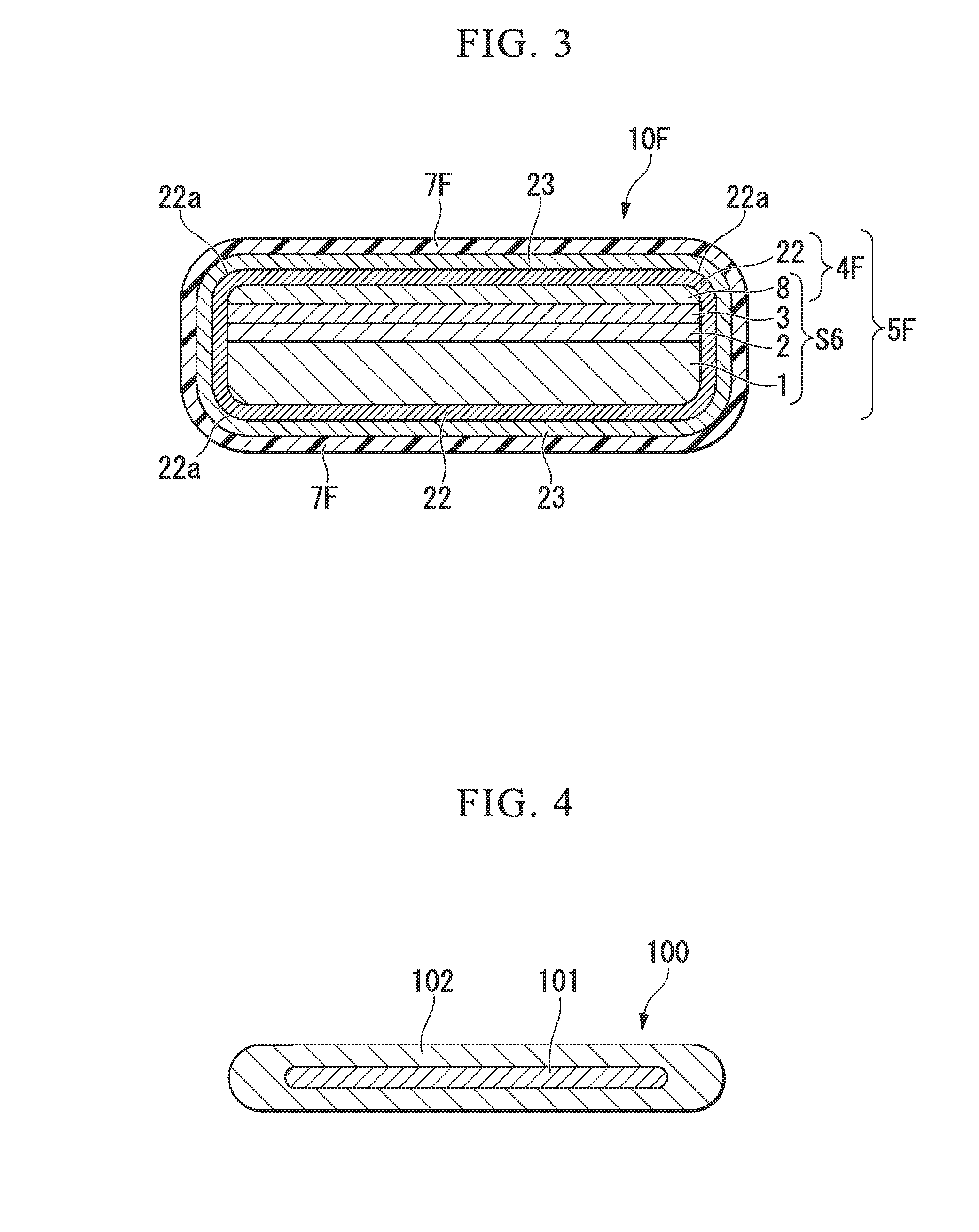
[0092]FIG. 3 is a schematic cross-sectional view along the width direction of a high-temperature superconductor wire according to a third embodiment of the present invention.
[0093]In a high-temperature superconductor wire 10F shown in FIG. 3, a laminated substrate S6 is formed by laminating an intermediate layer 2, an oxide superconductor layer 3, and a first stabilization layer 8 in this order on a substrate 1. In addition, a superconducting laminate 5F includes the laminated substrate S6 in the middle, and is formed by covering the entire outer periphery of the laminated substrate S6 with a second stabilization layer 22. The horizontal cross-sectional shape of the superconducting laminate 5F is an approximately rectangular shape. An insulation coating layer 7F that covers the entire outer peripheral surface of the superconducting laminate 5F is formed on the outer peripheral surface of the superconducting laminate 5F with a bonding layer 23 formed of tin interposed therebetween. T...
PUM
| Property | Measurement | Unit |
|---|---|---|
| Height | aaaaa | aaaaa |
| Surface roughness | aaaaa | aaaaa |
| Superconductivity | aaaaa | aaaaa |
Abstract
Description
Claims
Application Information