
Low-noise computer heat dissipation device

a computer and heat dissipation device technology, applied in the field of low-noise computer heat dissipation devices, can solve the problems of reducing high rotation speed of fans, and great noise, so as to reduce the noise of heat dissipation fans of the chassis and enhance the overall heat dissipation efficiency

Inactive Publication Date: 2014-12-11
ZHOU ZHEMING
View PDF25 Cites 9 Cited by
  • Summary
  • Abstract
  • Description
  • Claims
  • Application Information

AI Technical Summary

Benefits of technology

This patent is about a new computer heat dissipation device that reduces noise and improves overall heat dissipation efficiency. The device includes a central radiator and a low-speed fan to dissipate the heat generated by the computer chassis. The main heating members of the computer chassis, such as the CPU, graphics card, and memory, are connected to the heat conduction member, which is formed by heat pipes connected in series. The heat pipes are designed to minimize thermal interference and protect the heat pipes. The technical effects of the patent are reduced noise and increased heat dissipation efficiency.

Problems solved by technology

The defect of this method is that the sizes of the cooling fins mounted on the members are limited by the layout of the members, the heating dissipation area is usually small, and therefore there is high requirement for the wind speeds of the heating dissipation fans, which causes continuous high rotation speeds of the fans and great noise.
Furthermore, hot wind blown from the fans mounted on the heating members is prone to be inhaled by other fans, which may cause reduction of the overall heat dissipation efficiency.

Method used


Image

  • Low-noise computer heat dissipation device
  • Low-noise computer heat dissipation device

Examples


Embodiment Construction

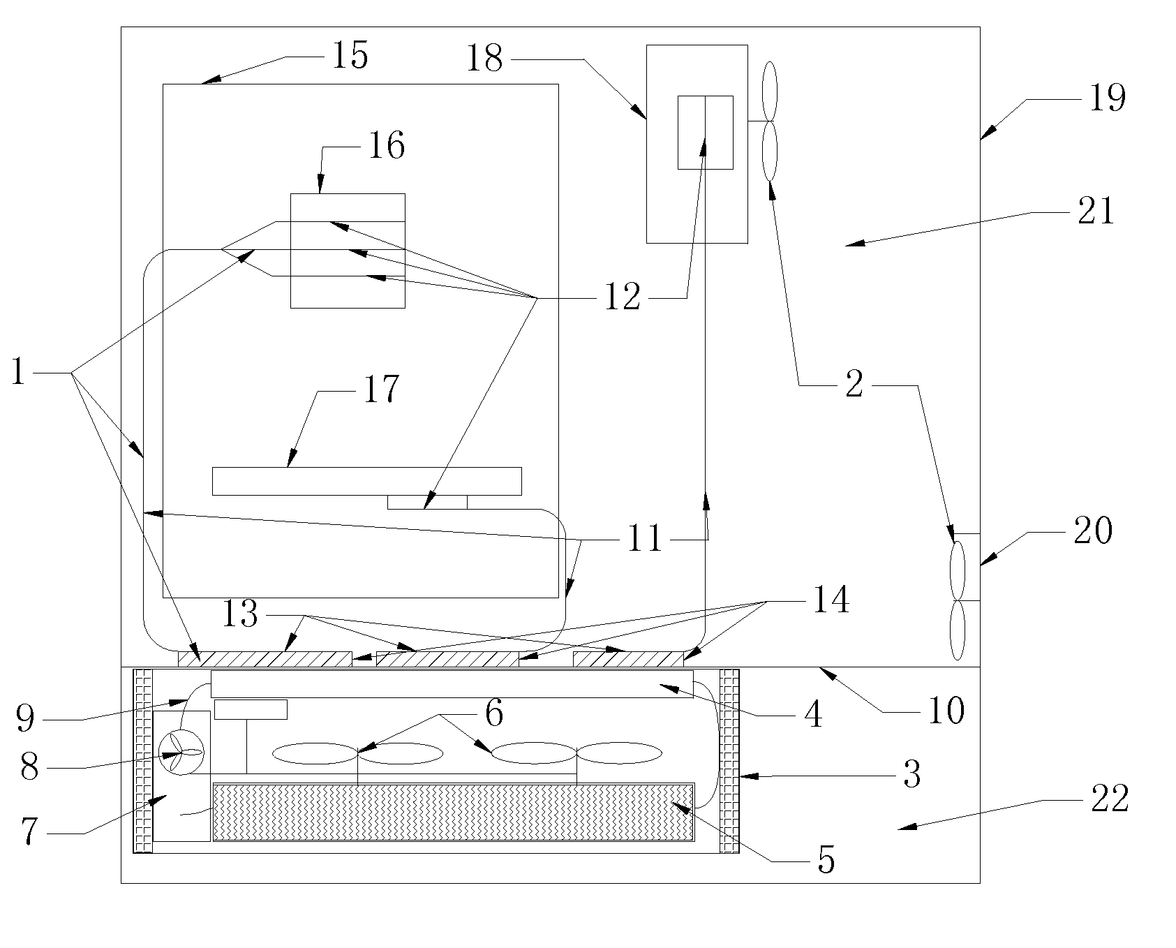
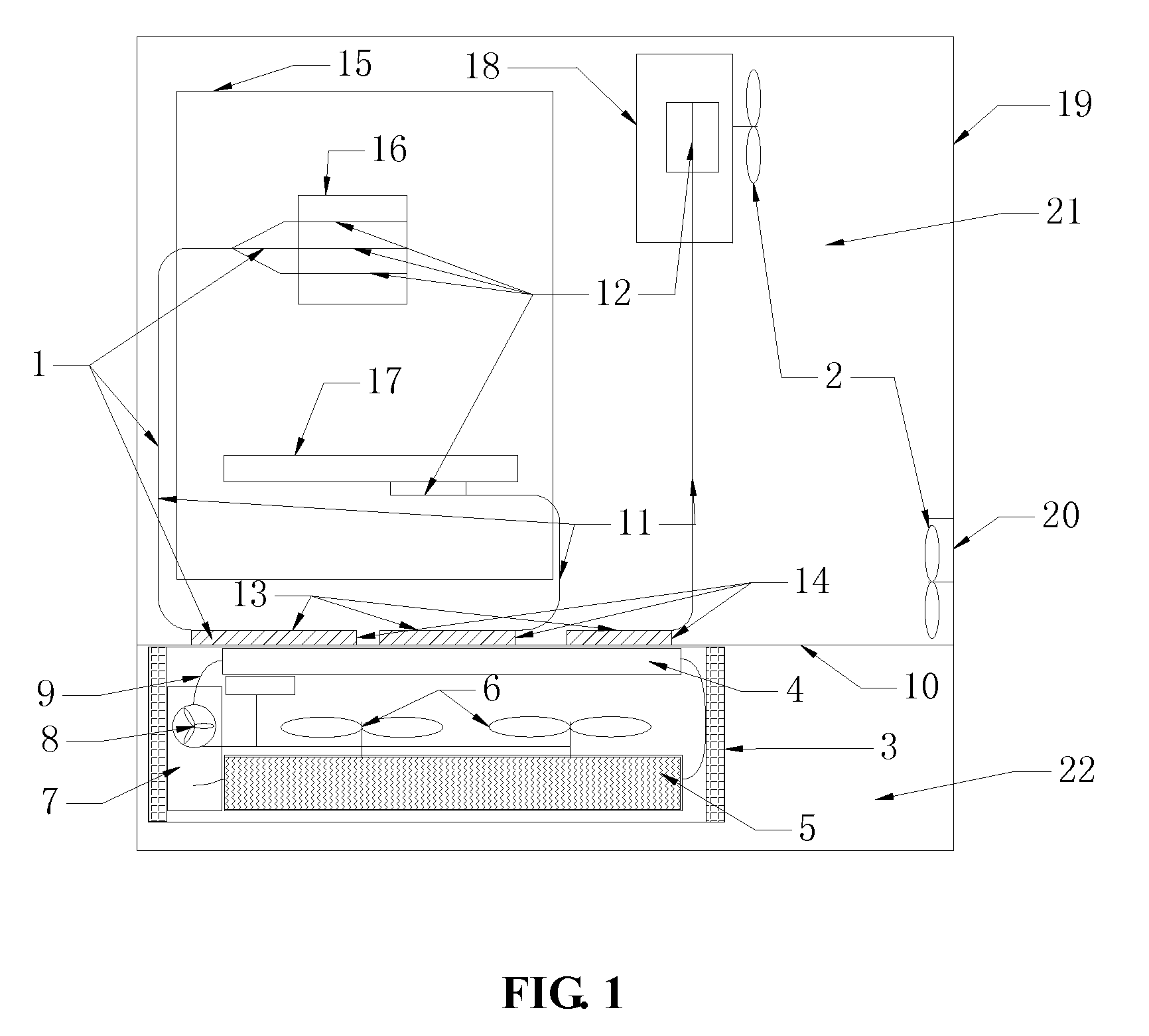
[0039]The following accompanying drawings and embodiments of the present application will be further described.

[0040]In FIG. 1, one embodiment of the present application is a PC chassis.

[0041]As shown in FIG. 1, the PC chassis includes a chassis housing 19, and a heat conduction member 1, auxiliary heat dissipation fans 2, and a central radiator 3 inside the chassis. The heat conduction member 1 is mainly formed by heat pipes 11, evaporation ends 12 of the heat pipes 11 are connected to main heating members, such as a CPU 16, a graphics card 17, and a power supply 18 in the chassis, and heat dissipation plates 14 are welded on condensation ends 13 of the heat pipes 11. The central radiator 3 is a water-cooling radiator, and includes a water-cooling plate 4, a radiator 5, a low-speed fan 6, a water storage tank 7, a water pump 8, a water pipe 9, and a water-resisting layer 10. The water-resisting layer 10 is mounted in the chassis to divide the chassis into an inner cavity 21 and an ...


PUM


Abstract

The present application discloses a low-noise computer heat dissipation device, which relates to electronic devices, and more particularly to the dissipation of heat generated by computer devices such as a server, a network device, a personal computer (PC), a notebook computer, etc. The computer heat dissipation device comprises a heat conduction member, a central radiator, and auxiliary heat dissipation fans. The heat conduction member is mainly formed by heat pipes, evaporation ends of the heat pipes are connected to main heating members inside a chassis, condensation ends of the heat pipes are connected to the central radiator, and the central radiator has cooling fins with large heat dissipation areas and a low-speed fan. The advantages of this technical solution are that noise of heat dissipation fans of the chassis can be reduced and the overall heat dissipation efficiency can be enhanced.

Description

CROSS-REFERENCE TO RELATED APPLICATIONS[0001]This application is a continuation of International Patent Application No. PCT / CN2013 / 071804, with an international filing date of Feb. 22, 2013, designating the United States, now pending, which is based on Chinese Patent Application No. 201220060220.X, filed Feb. 23, 2012. The contents of these specifications are incorporated herein by reference.BACKGROUND OF THE INVENTION[0002]1. Field of the Invention[0003]The present application relates to electronic devices, and more particularly to the dissipation of heat generated by computer devices such as a server, a network device, a personal computer (PC), a notebook computer, etc.[0004]2. Description of the Related Art[0005]Currently, the most common heat dissipation method for computer chassis is to mount cooling fins and fans on main heating members inside the chassis for heat dissipation. The defect of this method is that the sizes of the cooling fins mounted on the members are limited by...

Claims


Application Information

Patent Timeline
Patent Type & Authority Applications(United States)
IPC IPC(8): G06F1/20
CPCH05K2007/20027G06F1/20G06F1/203H01L23/427G06F2200/201H05K7/20809H01L23/467H05K7/20009H01L2924/0002H01L2924/00
Inventor ZHOU, ZHEMINGZHOU, FAMING
Owner ZHOU ZHEMING
Learn More