
Electric heating device and air conditioner

A technology of electric heating device and heat sink, which is applied in the direction of heating method, air conditioning system, heating element shape, etc. It can solve the problems of poor gas convection and heat conduction, difficulty in dissipating heat from the heating aluminum tube, and poor air flow in the air duct of the indoor unit. Smooth and other problems, to achieve the effect of reducing the total value of heating noise, increasing gas convection flow and heat conduction, and reducing resistance

Active Publication Date: 2016-08-31
GREE ELECTRIC APPLIANCES INC
View PDF6 Cites 0 Cited by
  • Summary
  • Abstract
  • Description
  • Claims
  • Application Information

AI Technical Summary

Problems solved by technology

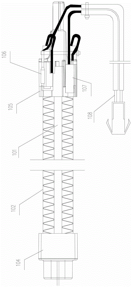
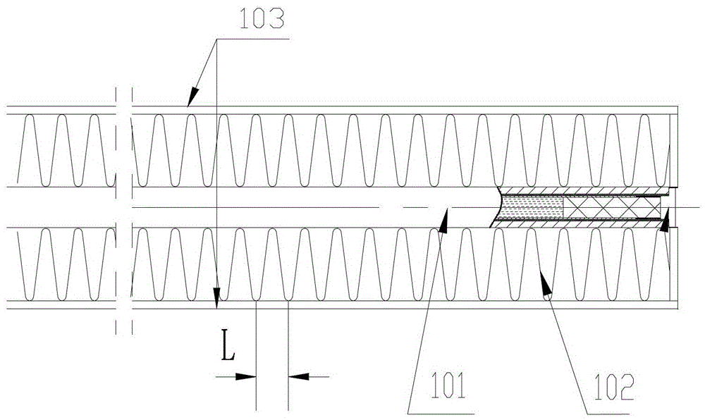
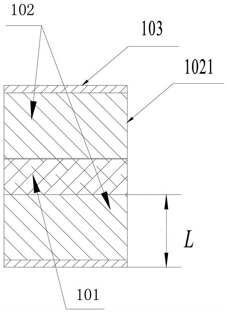
Due to the narrow space of the air duct of the indoor unit of the air conditioner and the heat sink structure design of the traditional electric heating device, such as image 3 , the existing electric heating device includes a heat pipe 101, a heat sink part 102 and a reinforcing plate 103, the reinforcing plate 103 is located on the outside of the heat sink part 102, and the cross-sectional shape of the heat sink part 102 is a rectangle, because the heat sink part 102 pairs The blocking effect of air duct air flow leads to poor air flow in the air duct of the indoor unit, and the gas convection and heat conduction effects of PTC electric heating are not good, making it difficult for the heat emitted by the heating aluminum tube itself to dissipate, and the PTC components work for a long time in high temperature reduction , the power is reduced, and it is easy to generate abnormal heating noise, which directly affects the noise performance of the air conditioner

Method used


Image

  • Electric heating device and air conditioner
  • Electric heating device and air conditioner
  • Electric heating device and air conditioner

Examples


Embodiment

[0050] Embodiment is described as follows in conjunction with accompanying drawing:

[0051] Such as Figure 4a , 4b As shown, the cross-section of the heat sink of the electric heating device is designed as a porous cross-section, and the heat dissipation through-holes 1022 are symmetrically distributed on the heat sinks on both sides of the heating aluminum tube, and each side of the heat sink has a circular hole with a diameter of 2mm and a side length The diamond-shaped hole is 1.7mm, and the hole diameter is moderate to maintain the heating effect of the electric heater. The hole spacing S is 6mm, and the distance S1 between the hole center and the heating aluminum tube is 4.5mm, so that the heat of the heating aluminum tube can be fully dissipated through the heat sink. The distance S2 between the heat dissipation through hole 1022 and the wide side 1021 of the heat dissipation fin is 4.6 mm to avoid heat concentration. The distance S3 between the heat dissipation thr...


PUM


Abstract

The invention provides an electric heating device and an air conditioner. More than one radiating through hole which penetrates through the two ends of a radiating fin component is formed in the radiating fin component, and an electric heating device of the air conditioner is positioned beside an evaporator and is arranged in an air-inlet area of a ventilating device. Therefore, the structure of the radiating fin of the electric heating device is improved, the radiating fin is designed into the shape of a porous cross section in the way that the radiating fin is perforated, the shapes and distribution of the holes are designed according to the structure of the indoor unit and the electric heating device of the air conditioner, air flowage in the electric heating device is improved, the heating efficiency of a PTC (positive temperature coefficient) element is improved, meanwhile, the resistance of the electric heating device to air flow is reduced, air flowage in the electric heating device is improved, air convection and heat conductivity are increased, the efficiency of the electric heating device is improved, the total heating noise of the air conditioner is reduced by about 2 to 3dB (A), meanwhile, the maximum peak of the noise is reduced, abnormal noise is eliminated, and the noise performance of the air conditioner is improved.

Description

technical field [0001] The invention relates to the technical field of refrigeration and air conditioning, in particular to an electric heating device and an air conditioner. Background technique [0002] When the heat pump air conditioner is running under heating conditions, it exchanges heat with the outside through the heat exchanger to achieve the purpose of heating the indoor environment. When the heat pump air conditioner is used in winter, the heating capacity of the system will gradually decrease as the temperature decreases. . Usually, in order to make up for the shortcoming of poor heating capacity under low temperature conditions, a PTC electric heating device is added to the air conditioner. Adjust the indoor temperature to achieve the purpose of rapid and powerful heating, and has the characteristics of stable performance, safety and no open flames, etc., making the PTC electric heating device the main auxiliary electric heating method for air conditioners at p...

Claims


Application Information

Patent Timeline
Patent Type & Authority Patents(China)
IPC IPC(8): F24F13/00H05B3/42F24F5/00F24F13/24
Inventor 刘攀邹建煌刘中杰李广湘唐晓晖周英俊
Owner GREE ELECTRIC APPLIANCES INC
Learn More